|
 |
Circuits designed by David Johnson, P.E.
Last Updated on:
Saturday, December 23, 2017 03:21 PM
List of Dave's Circuit Designs
The contents & graphics
of Discovercircuits.com are copyright protected.
LINKING to Dave's circuits is permitted but DO NOT COPY any files to your WEB
SITE server |
|
|
|
|
|
More
Beeper & Buzzer Circuits
Doorbell Circuits Star Trek Doorbell
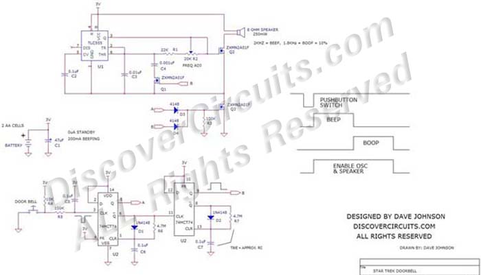
In the Star Trek “Next Generation” TV series, the doorbell outside the private
quarters of a crew member makes a particular “beep-boop” sound. The 3v battery
powered circuit below tries to simulate this sound. The circuit uses one 74HCT74 dual
D flip/flop IC, wired as two one-shot circuits. Both are designed to produce a
pulse about one half second long. The first pulse turns on a 555 timer to form
the beep sound.
|
| The
second flip/flop one shot turns the 555 timer circuit and turns on an n-channel FET, which
switches in an extra capacitor, to make the “boop” sound. To my ears, I think the
beep sound is right around 2KHz, while the boop sound is about 10% lower at about 1.8KHz.
A variable resistor sets the beep sound frequency. The output of the 555 timer feeds a low
power 8 ohm speaker using a buffer n-channel FET. A diode “or” gate and another FET
enables the speaker and time circuit. Each time the pushbutton switch is pressed,
the circuit should produce the beep-boop sound. I have observed that some 74HCT74 ICs do not always operate correctly in this circuit. Some devices have a poor
Schmitt trigger action on their inputs. Let me know if you have problems. |
|
|
Click
on Drawing Below to view PDF version of Schematic |
|
 |
|
|
|