|
A
Long-Delay
Op-Amp
Timer
submitted by:
Frank Sutherland
lingua@iafrica.com
Feb 2005
Last Updated on:
Wednesday, June 02, 2021 01:44 PM |
|
| |
|
I recently had
to design a timer to switch off a small fan after two or three hours. The period was
not critical, but it was important that the circuit should never fail to time out.
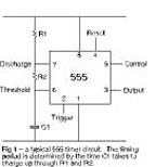
This requirement precluded the use of a 555, because in a 555 circuit the period is
determined by the time it takes for a capacitor to charge up through a resistor
(typical circuit shown in fig 1). Long intervals require high-value resistors
and large electrolytic capacitors, and this brings two problems. The first
problem is that an electrolytic capacitor has an internal leakage current, and
the second is that the 555 draws a small current – about 0,1 µA – into pin 6. These
two currents tend to cancel out the charging current flowing into the capacitor
through R1 and R2. If the total of the two currents is a significant proportion of the
charging current, the timing period will not be as designed. If the total equals
the charging current, C1 will not charge up beyond a given level and the circuit will
never time out. |
| |
|
|
 |
 |
|
The conventional
way to obtain longer periods is to use a 555 timer to generate pulses at say one per
second, and then use logic divider ICs to extend the pulse time by a factor of two,
four, eight, sixteen, etc. I have used such a timer myself to de-ice a refrigerator,
but in the situation to hand it seemed like overkill. |
|
|
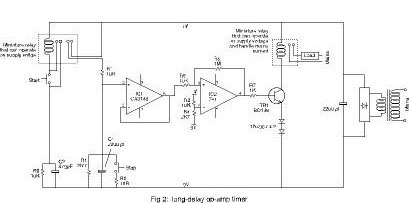
| After
some experimentation I ended up with the circuit shown in Fig 2. It comprises a timing
capacitor, a FET-input 3140-type IC configured as a voltage follower, and a second IC,
a 741, which functions as a voltage comparator and relay driver. |
|
| To start
the timer, the timing capacitor, C1, must be charged up. The first prototype simply
had a push-button just above R1, but it soon appeared that a quick tap on the button
would result in C1 being only partially charged. Hence I added a small relay with two
sets of contacts. The first set causes the relay to latch for a second or two
(until C2 is charged up), while the second set passes current to charge C1. |
| Once
charged, C1 begins running down through R2. |
| The top
of C1 is connected to the non-inverting (+) input of IC1, so this input must not
provide a discharge path. This is why the FET- input 3140 was chosen for this
position. The impedance at its inputs is around 1,5 million megaohms, which means that
for all practical purposes the inputs are open circuit. |
|
The inverting (-) input of IC1 is
connected directly to the output, so that the gain of the stage is one. Thus the
output voltage of IC1 follows the voltage at the (+) input. It falls gradually as C1
runs down. |
| The
“stop” button simply discharges C1. |
| IC2 is
configured as a voltage comparator and "click-over" switch. When C1 is charged up the
voltage at the (+) input of IC2 is above that at the (-) input, which is set at about
one fifth of the supply voltage by R3 and R4. The output of IC 2 is then high, and
base current flows to TR1 through R7. TR1 turns on, the relay pulls in and the load
receives power. |
| As C1
runs down, the voltage at the output of IC1 and hence the (+) input of IC2 falls. When
the voltage goes below the voltage at the (-) input, the circuit clicks over and the
output goes low. The positive feedback supplied by R5 and R6 ensures a clean
"click-over" without oscillation. TR1 then cuts off and the relay opens. |
|
|
| With the
component values shown, the circuit gives a reliable timing period of 150 minutes --
give or take a minute or two. A larger capacitor and/or a higher-value resistor will
give a longer period, but again the period could vary if the leakage current in the
capacitor should be high enough to "compete" with the discharge current through R2.
However, the circuit will never fail to time out. Upping the value of C1 to 10 000 µF,
by way of experiment, gave a timing period of 14 hours and 55 minutes – give or take
three minutes or so. |
| The
components shown in Fig 2 are not the only ones that will do the job -- they are the
ones I had in my scrap-box. Many other op-amps and transistors will do in the place of
the 741 and the BD139, and the user will no doubt experiment with whatever relays he
has to hand. |
| When
experimenting, remember that a voltmeter connected to the top of C1 will provide a
discharge path to ground and will thus affcect the timing period. Connect the
meter to the output of C1, but then bear in mind that the output can only rise to
about two volts below the supply voltage. Thus, if the supply is 12V and C1 is
charged up to this voltage, the IC1 output will only read about 10V and will “idle”
there until C1 has run down some way. |
|
The circuit
should be powered from a supply of 12V24V. This supply need not be regulated but
must be reasonably stable, since large voltage variations could affect the operation
of the voltage-comparator part of the circuit. The relay coil voltages should match
the supply voltage, and the supply should be able to deliver the current required by
the relays -- plus 10 mA or so for the two ICs. |
|
|
|
|
|