|
1 Watt 2.45 GHz Linear Amplifier using RF Micro Devices RF2126 - Schematic Only __ Designed by Michael Micili
1 Watt Audio Amp using a TDA7052 - Ham RadioSchematic __ Designed by Guy Roels ON6MU
1 Watt Class-C Amplifier - schematic only, no circuit description __ Contact: Charles Wenzel of Wenzel Associates, Inc.1.5 Volt Amplified Ear - Useful to listen in faint sounds1.5-Volt Battery operation, includes electret microphone preAmplifier which runs from1.5-Volt DC and can directly drive32 Ohms impedance mini-earphones __ Contact: Flavio Dellepiane, fladello @ tin.it
1.5V iPod Microphone - Works with: 3rd & 4th Generation and the original color iPods. Does not work with: 1st, 2nd & 5th Generation, nano, mini or shuffle iPods __ Designed by © Scott Mitchell
10 W Experimental Output & 1 Meter Loop Antenna for 187 kHz Lowfer - This page describes an antenna, a 1 watt final output stage, and a transformation network for radio experiments at 187 kHz __ Designed by Rod Elliott ESP
10 watt audio power Amplifier using discrete transistors (includes PCB layout) - Schematic only, no circuit description included] __ Acknowledgements The 10W amplifier is taken from "Transistor Audio and Radio Circuits" published Mullard
10 Watt Mini Audio Amplifier - You can use this powerful amplifier in any small audio project. It is very small (6.5 x 4.5 cm). It outputs 10W and uses a 9V battery.
10 Watt Power Amplifier - This page describes an antenna, a 1 watt final output stage, and a transformation network for radio experiments at 187 kHz __ Designed by J. L. Linsley Hood, M.I.E.E.
100 W Audio Amplifier - This is an exceptionally well designed amplifier, with a lot of power reserve, high fidelity, low distortion, good S/N ratio, high sensitivity, low consumption and full protection. __ Designed by © smart kit electronics
100 W Audio Amplifier - During my free time, I have acquired abilities with electronics. Music also being one of my hobbies, I decided to use my electronic knowledge to build an audio amplifier. My amplifier is not the most powerful that exists, but it outputs a nice quality of sound. Also, it has successfully passed the "party test". This means it has played as loud as possible without distortion for almost 6 hours, in a 3 ohms load __ Designed by Raphaël Assénat
100 Watt Amp - Here is a simple and cheap amp to make. I could have made the circuit board smaller but "what the heck" __ Designed by Jon Tirone, AKA John Fisher
100W FM Amplifier - This Power amplifier is equipped with a bipolar transistor, the famous MRF317 As lots of FM amplifier application , the power transistor is in a C class bias. All the impedance networks (Input & Output) have been determined by using the __ Designed by Michel P
100W Guitar Amplifier - Guitar amplifiers are always an interesting challenge. The tone controls, gain and overload characteristics are very individual, and the ideal combination varies from one guitarist to the next, and from one guitar to the next. There is no amp that satisfies everyone's requirements, and this offering is not expected to be an exception __ Designed by Rod Elliott ESP
100W HiFi MOSFET Amp - The neat thing about the series 5000 is that it was built around new (at the time) Hitachi lateral power MOSFETs. Most power MOSFETs (VMOS, trenchFETs, HexFETs etc) use a vertical structure, where the current flows vertically. This has the
100W RMS/Channel Stereo Amplifier-Part 3 - Final article covers the assembly of the remaining modules and includes the full wiring and setting up details. __ SiliconChip
101 AT Keyboard to ASCII Decoder using 68HC705J1A MCU - Why would you want to interface the Keyboard? The IBM keyboard can be a cheap alternative to a keyboard on a Microprocessor development system. Or maybe you want a remote terminal, just couple it with a LCD Module. Maybe you have a RS-232 Barcode Scanner or other input devices, which you want to use with existing software which only allows you to key in numbers or letters. You could design yourself a little box to convert RS-232 into a Keyboard Transmission, making it transparent to the software __ Designed by Craig Peacock
10-14W Class a Amplifier - I have built this amplifier and it does sound good. It requires a preamp as it hasn't got much gain. It requires big heat sinks and a large transformer and a great power supply and careful wiring, but in the end it is extremely simple and it sounds very good. The zener diode rejects any ripple coming from the power supply, But you still only want a ripple of 10mV max. The ripple reaching the input is amplified, so the zener gets rid of that, but whatever ripple there is will still reach the power stage.
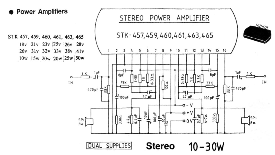
10-30 watt stereo Audio Amplifier - Schematic only, no circuit description
10W Audio Amplifier with Bass-Boost - High Quality, very simple design No need for a preAmplifier __ Contact: Flavio Dellepiane, fladello @ tin.it
10W Class D power Amplifier - Class-D audio amplifiers with TDA7480. The main selling point of this amplifier is the very low dissipated power compared to normal class AB amplifiers. Only a small "on board" copper area heatsink is required for normal operation. The IC has built-in stand-by and mute feature, overvoltage protection, short circuit protection and thermal overload protection. __ hobbyteam @ hobby-hour.com
10W Mini Audio Amplifier - You can use this powerful amplifier in any small audio project. It is very small (6.5 x 4.5 cm). It outputs 10W and uses a 9V battery. __ Contact: IQ Technologies
12 Volt 5 Watt Amplifier - This solid state amplifier uses 10 transistors and 5 diodes. It can deliver 5 Watts into a 4 ohm loudspeaker and about 3 Watts into an 8 ohm loudspeaker. It is made using Chinese transistors from the 1970's and 1980's. __ Designed by Julius Chen
12 Volt powered, 4x15 Watt Audio Amplifier - Using car audio chips and intended for installation inside a computer. __ Designed by Manfred Mornhinweg
12 WATT audio amplifier with tone - Ham RadioAudio Amplifier Schematic __ Designed by Guy Roels ON6MU
15 Watt Amplifier - A 15 watt amplifier made using discrete components by Sergio García de Alba Garcin from Guadalajara, Mexico. __ Designed by Sergio García de Alba Garcin
150 Watt Amplifier - This is the cheapest 150 Watt amplifier circuit you can get, I think. Based on two Darlington power transistors TIP142 and TIP147, this circuit can deliver a blasting 150 W Rms to a 4 Ohm speaker. Enough for you to get rocked?, then try
150W Audio Amplifier that's cheap to build using TIP142 / TIP147 Darlington power transistors - This is the cheapest 150 Watt amplifier circuit you can make, I think. Based on two Darlington power transistors TIP 142 and TIP 147 , this circuit can deliver a blasting 150 W Rms to a 4 Ohm speaker. Enough for you to get rocked?;then try out this.
16 Watt Amplifier - This circuit provides 16 watts of amplification. it is built using two LM383 power audio amplifiers. use suitable heat sinks with the IC's. __ Designed by Andy Wilson
18W Audio Amplifier - High Quality very simple unit -- No need for a preamplifier __ Contact: IQ Technologies
19 Watt Amplifier using LA4440 - This is the circuit diagram of a simple 19 watt amplifier using IC LA4440 from Sanyo. It uses very less components other than the IC LA4440. A very high quality circuit with respect to its cost and ideal for beginners.
1-capacitor powers audio mixer - 03/14/97 EDN-Design Ideas Micro power and low-voltage op amps allow you to build high-performance analog-signal processors that require no batteries or wall transformers, this simple mixer is powered using one large capacitor such as a Supercap or Dynacap for some Time Design by Aleksandr Belousov, Rego Park, NY
1W Audio Amplifier with Compressor - Schematic only __ Designed by va3iul
1W Audio Amplifier with Voltage Regulators - A simple stereo audio amplifier is built around two 7905 negative-voltage regulators (IC1 and IC2) and a few discrete components. The circuit will also work with other 79XX regulators if appropriate power supply is used. Regulator IC 7905 works as an amplifier for the voltages applied to common pin2 (Ground or GND). Also check __ Designed by Popescu Marian
|