|
2-channel guitar preamplifier, Pt 1 - Each channel has bass, mid and treble controls and there's an optional digital reverberation unit as well. __ SiliconChip
2-Channel Guitar Preamplifier, Pt 2 - Add life to your music with this easy-to-build digital reverberation board. It uses two digital delay chips to give realistic effects. __ SiliconChip
2-channel Guitar Preamplifier, Pt 3 - Pt.3: Building the preamps and reverb module into a metal rack case __ SiliconChip
2-Channel Power Amplifier - The design of our power amplifier is based on a general purpose power amplifier widely used in the electronics world. The chip (NTE 1606) we are using is used in many consumer stereo systems. We did some research and came out with a simple design that uses the NTE 1606 Power Amplifier chip
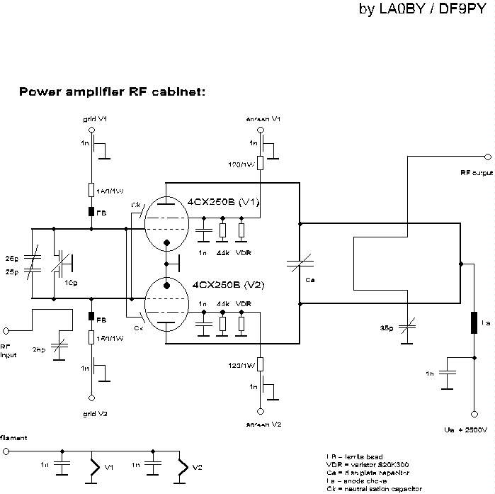
2m power Amplifier - Schematic only, no circuit description __ Designed by LA0 DF9PY
2m-20m Transverter - This little circuit is a transmitting and receiving converter (transverter) that converts a FT290 or similar multimode handheld transciever to the 14MHz amateur band. The project is a single board module that needs an external local oscillator, for example, the VHF harmonic oscillator (or QRP VHF FM TX) LO for transverter project. It should be a relatively simple matter of scaling coils __ Designed by Harry Lythall-SM0VPO
2Mhz Broad Band Optical Fiber Receiver - If you need more sensitivity than the above circuit this circuit provides about ten times more gain. It too is designed around an inexpensive plastic optical fiber detector . . . Hobby Circuit designed by David A. Johnson P.E.-June, 2000
2N2222 40 Meter CW/DSB Tranceiver - In spring of 1998, NorCal sponsored a contest to design and build a project using no ICs and 22 or fewer 2N2222s as the active semiconductor devices. I thought this was a really intriguing idea, so I set about to design my version __ Designed by Monty Northrup
3.3V Baseband Video Splitter/Cable Driver (DC Coupled) - A simple video splitter application using an LT6206. Both amplifiers are driven by the input signal and each is configured for a gain of two, one for driving each output cable. Here again careful input biasing is required (or a negative supply as suggested previously). __ Linear Technology/Analog Devices App Note, Mar 25th 2010
3.3V Single Supply LT6551 RGB Plus SYNC Cable Driver (DC Coupled) - The LT6551 drives four cables and operating from a single 3.3 V supply. The inputs need to have signals centered at 0.83V for best linearity. This application would be typical of standard-definition studio-environment signal distribution equipment (RGBS format). __ Linear Technology/Analog Devices App Note, Mar 25th 2010
30 Watt Power Amplifier - This is an unusual circuit for an ultra-low distortion power amp. According to my original notes the circuit is dated January 1977 so the circuit is not exactly modern but it is still sufficiently different to be interesting. The circuit was designed and sold as a card by a purveyor of surplus components but, even using mostly manufacturer's rejected transistors, we managed to get about 0.02% total harmonic distortion at 30 watts with a ±25v power supply into 8 ohms. : no bad figure even in these days of MOSFET and ICs. In 1977 anything below 0.1% was considered excellent. And this figure was pretty repeatable without doing much selection. __ Designed by Richard Torrens
300 Watt Subwoofer Power Amplifier - There are some important updates to this project, as shown below. Recent testing has shown that with the new ON Semi transistors it is possible to obtain a lot more power than previously. The original design was very conservative, and was initially intended to use 2SA1492 and 2SC3856 transistors (rated at 130W)with 200W (or 230W) devices, some of the original comments and warnings have been amended to suit. __ Designed by Rod Elliott ESP
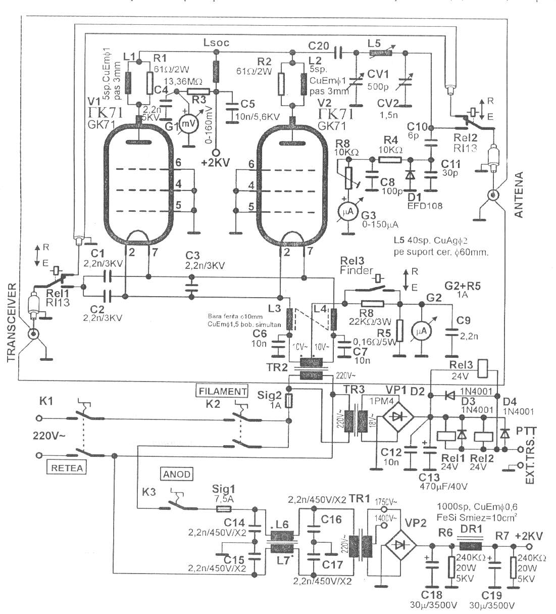
350W QRO with GK71 for 160-15m - Schematic only, no circuit description __ Designed by © 2001YO5OFH, Csaba Gajdos
3mw Laser Test-20Mhz VCSE - L - This circuit takes advantage of some new vertical cavity surface emitting lasers (VCSEL) that don’t require light output control circuits. The circuit shows how to drive the device from a single high speed CMOS
IC . . . Hobby Circuit designed by Dave Johnson P.E.-June, 2000
4 channel power Amplifier with bi-amping & bridging options - After building the Micro-Amp, I was not only impressed with the performance of the LM4780, but also felt ready to tackle a more ambitious metalwork project. This is the result: four channels, with options for bi-amping and bridging. __ Designed by Mark Hennessy
400MHz, 5V Single Supply Video Driver (AC Coupled) - The LT6557 400MHz triple video driver is specifically designed to operate in 5V single supply AC-coupled applications as shown. The input biasing circuitry is contained on-chip for minimal external component count. A single resistor programs the biasing level of all three channels. __ Linear Technology/Analog Devices App Note, Mar 25th 2010
432 MHz kilowatt Amplifier - Schematic only, no circuit description __ Designed by W1QWS
45W HEXFET Power Amplifier - An ideal solution to make a good, low cost power amplifier. __ Designed by Sam
4-Watt AF Amplifer - I have recently included a page about AF amplifers for use with Homebrew rigs. In this I mentioned that I may include a practical one-watt circuit, complete with PCB foil and layout. Here it is, but I have taken the liberty of engineering it to provide 4-watts of AF output and with a frequency response almost suitable for Hi-Fi applications __ Designed by Harry Lythall-SM0VPO
5 Band Graphic Equalizer using a Single IC/Chip - This circuit uses a single chip, IC BA3812L for realizing a 5 band graphic equalizer for use in hi-fi audio systems. BA3812L is a five-point graphic equalizer that has all required functions integrated onto one IC. IC is comprised of five tone control circuits and input and output buffer Amplifiers __ Designed by Paul S
5 Watt HF CW transmitter - This is a very simple 5 watt CW TX based upon a TTL logic chip. There is just one "tricky" component and this is Cx. This component should have an impedance of about 1050 ohms at the frequency of interest. If you wish to reduce the transmitter power, increase the value of Cx. It is Cx which causes the square wave from the output transistor to approximate a sine waveform. The value of Cx is the price of simplicity in this TX __ Designed by Harry Lythall-SM0VPO
5 watt mini-amplifier 28Mc (or 27Mc CB) with one transistor - Ham RadioV-U)HF AMPLIFIERSchematic __ Designed by Guy Roels ON6MU
50/60Hz Sync Generator-Fully Isolated - This circuit will produce a single pulse at the zero voltage cross points of the power line voltage. An opto-coupler provides a very safe 5KV isolation. . . Circuit by David A. Johnson P.E.-December, 2004
500mW HF Linear Amplifier - his project was a particular surprise for me in that the BC547 (equiv 2N2222) can be used to build a 500mW linear amplifer covering the entire HF band with excelent spectral purity and no neutralising at all. Ugly-bug construction was used but I dare say that the good results are partly to do with the method of construction. __ Designed by Harry Lythall-SM0VPO
50Mhz Broad Band Optical Fiber Receiver Version A - If the above circuit it still too slow, you can try this circuit. What it lacks in sensitivity it makes up for in speed. The circuit attaches a plastic fiber optic PIN photodiode assembly to a small box containing a small 3v battery and a standard. . . Circuit by David Johnson P.E.-June, 2000
50MHz power Amplifier - Schematic only, no circuit description __ Designed by JH0WJF
55 Watt Originally 75W Power Amplifier - The AKSA is a highly refined push pull solid state stereo amplifier of 55W per channel. It was developed to overcome most of the sonic problems of transistor amplifiers, and incorporates some highly innovative thinking from an experienced designer. It delivers stunning resolution and a pure, sweet sound at very low cost __ Designed by Project from Hugh Dean in Melbourne, Australia
555 Amplifier - The 555 can be used as an amplifier. It operates very similar to pulse-width modulation. The component values cause the 555 to oscillate at approx 66kHz and the speaker does not respond to this high frequency. Instead it responds to the average CD value of the modulated output and demonstrates the concept of pulse-width modulation. The chip gets very hot and is only for brief demonstrations. __ 555-Timer
5Mhz Broad Band Optical Fiber Receiver - This circuit is a simple broad band light detector that uses a very inexpensive IC and a PIN photodiode that is packaged for use with plastic optical fibers. It has a bandwidth from 1KHz to over 5MHz. It is great for experimenting with various modulated. . . Circuit by David A. Johnson P.E.-June, 2000
5W QRP with KT907 - Schematic only, no circuit description __ Designed by © 2001YO5OFH, Csaba Gajdos |
