|
Aircraft Receiver Circuits
Last Updated on:
Wednesday, June 02, 2021 01:44 PM |
|
|
Links to electronic circuits, electronic schematics and designs for engineers, hobbyists, students & inventors:
|
|
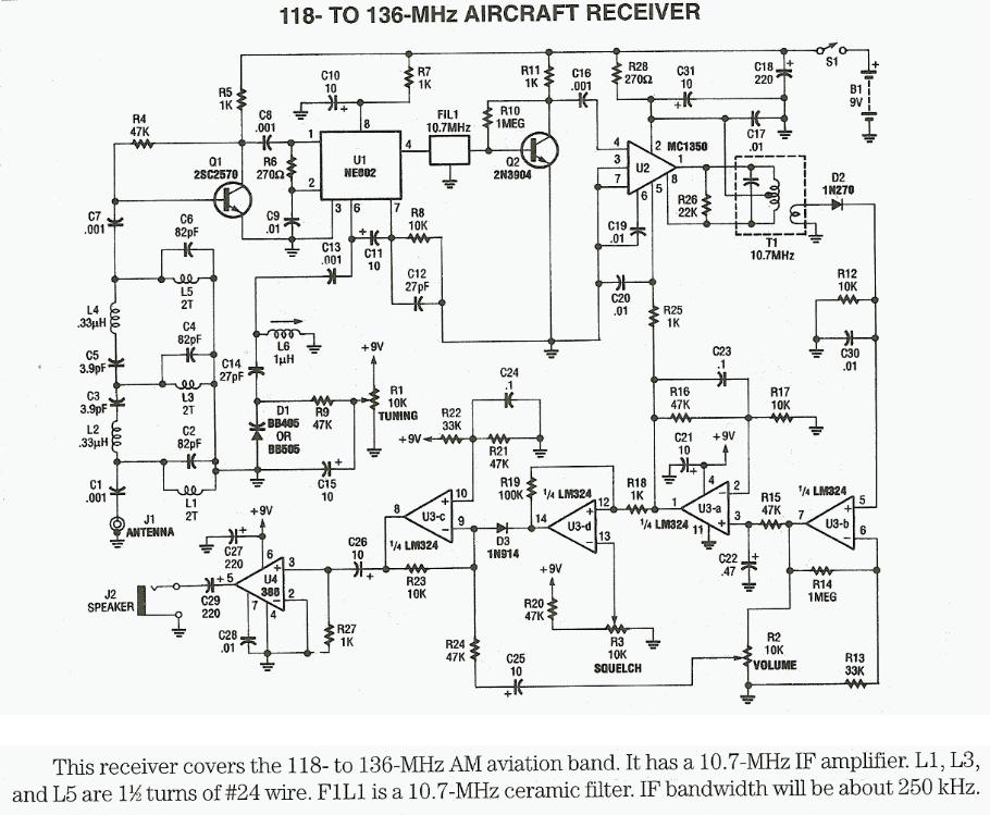
118MHz to 136MHz aircraft receiver - Schematic only, no circuit description
Aircraft Radio Communications Receiver - The communications between commercial aircraft and the ground can be interesting, amusing and sometimes even disturbing. However radios that receive the approximately 220MHz to 400MHz band commonly used for aircraft (both military and commercial) are not easily found. And scanners can be complicated, large and expensive. With an easy to build circuit such as this one, everyone can enjoy listening in on these conversations. __ Designed by Aaron Cake |
|
|
|
Aircraft Receiver - The Passive Aircraft Receiver is basically an amplified "crystal radio" designed to receive nearby AM aircraft transmissions. The "passive" design uses no oscillators or other RF circuitry capable of interfering with aircraft communications so it should be fine inside the cabin of the aircraft. Nevertheless, check the regulations before using this receiver on a commercial airliner __ Contact: Charles Wenzel of Wenzel Associates, Inc.
AM Receiver for Aircraft Communications - This receiver is controlled by a Frequency Synthesizer Circuit. The receiver is VERY stable, low noise-level and easy to build and tune __ Contact:
info @ rfcandy.biz |
|
|
Aviation Band Receiver - Figure 1 shows a schematic diagram of the Aviation Receiver--a super heterodyne AM (Amplitude Modulated) unit built around four IC's: an NE602 double balanced mixer (U1) , an MC1350 linear IF amplifier (U2) , an LM324 quad op-amp (U3) , and an LM386 audio amplifier (U4). In operation, an antenna that plugs into J1 picks up the AM signal. That signal is then coupled through C1 to a three-section, tuned-filter network consisting of L1-L5 and C2-C6 __ Designed by Tony van Roon VA3AVR
Inductively sense aircraft engine valve position - 04/25/14 EDN-Design Ideas Aircraft engine designers are conservative by nature, but here's a way to improve performance anyway. This design uses an inductor to sense the position of a valve on an aircraft engine as a way to get camshaft position information. Knowing the camshaft position along with the crankshaft position allows fuel injection while the intake valve is open and the use of individual coils for each cylinder. Design by Angus McCamant |
|
|
Aircraft Circuits |
|
|