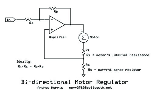
| This circuit shows
the concept I used in the drill motor control that I submitted earlier. I cam up
with it in 1994 when I built the device. My algebra and my patience are a bit too
rusty at my age now to write an equation that describes the relationship between the BEMF
of the motor and Vin. I've seen circuits like this
that use two opamps that separate the positive and negative feedback portions of the motor
control signal. They're easier to analyze mathematically. Still, the concept
is the same. The motor get a voltage applied to it that is proportional to the
control voltage, but with a sample of the motor current used as positive feedback to
compensate for the motor resistance loss.
Unless you use power opamps, this is one a concept
drawing. The ration of Rb/Ra cannot be greater that the ration of Ri/Rs, or it will
oscillate. It should be slightly less. Perfect speed control would require the
ratios to be the same, but that is not realistically possible. For one thing, brush
resistance varies with wear and during motor rotation. For precise control, you
canpt use carbon brushes. Not that cassette record motors have wire brushed in them.
If you amplifier supports it, this concept allows for
bidirectional rotation. |