|
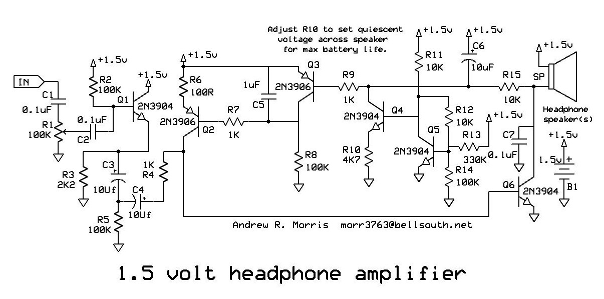
This circuit stabilizes the quiescent
voltage across the speaker at the exact level necessary to get the desired maximum
available volume at minimum battery draw. This more than doubles the battery life compared
to just connecting a simple resistor between the base and collector of the output
transistor. This (class A) type of amplifier is the only kind of amplifier that you can
use at such a low voltage with simple discreet components. A (class A) amplifier has a
maximum efficiency of 50% which is not great for batteries. Stabilizing the quiescent
current to the minimum necessary to do the job would be a big help. Also, to
minimize the chance of damaging the earphone, the amount of DC pushed through it should be
minimized.
I determined that 700mV P-P produced
plenty of volume with the headphones I was using. I therefore set the quiescent voltage
across the speakers to 370mV. I measured 12.5mA of battery draw and had plenty of volume.
The sound quality was surprisingly good. I think it’s worth the additional parts to more
than double the battery life. It may also allow the use of a smaller battery, which could
be a lot bigger deal than the added transistors.
Adjust the value of R10 to set the
desired quiescent voltage across the speaker(s). For maximum stability, Q3, Q4 and Q5
should be in very close temperature proximity with each other. The input impedance of the
circuit is approximately equal to R4 (1K in this case) without the buffer circuit (Q1) and
about 50K with the buffer circuit and volume control. If your circuit can drive the load
impedance of the amplifier itself you can leave out the buffer circuit which is everything
ahead of R4. In testing, I got unity gain with a 16 ohm load (both earphones) with a pot
set at 3.1K as R4. With one earphone (32 ohms), unity gain was established with 7.8K as
R4. The circuit was unaffected by battery voltage until it shut down at about 0.8 volts
(32 ohm load) and about 0.85 volts at 16 ohm load. Batteries are considered by the
industry to be depleted at 0.9 to 1.0 volts per cell. Note: You can increase the gain
and/or input impedance, possibly eliminating the buffer circuit (Q1) by replacing Q6 with
a BC337.
If you delete Q4 and Q5 and their
related components, the circuit will hold 0.55 volts across the speaker(s). If you need a
higher quiescent voltage, connect a resistor across C6. In the circuit shown here the gain
was measured at about 3 with a 16 ohm load. The gain of the circuit is set by R4 and
changes mainly with the beta of the transistor used as Q6. Battery voltage (within limits)
has little effect because Q1 is an emitter follower and the current through Q6 is
stabilized. |