|
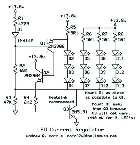
Here is a circuit that will allow LED's to
glow at a constant brightness throughout battery life or varying power supply voltage.
This circuits is capable of saturating, allowing the battery voltage to get within 0.3
volts of the LED voltage before the LEDs start to dim. This is far superior to just
using a current limiting resistor.
The circuits uses positive feedback to get
the tightest possible control of the LED current with just two transistors (Q1 and Q3). Q2
is added when powering multiple LED strings to prevent the first string from glowing
dimmer that the rest. Q2 and R4 can be deleted (connecting the collector of Q1
directly to the base of Q3) if only one string (or Just a few strings) of LED is being
used.
R3 starts the regenerative circuit up and D1
is temperature compensation for the Vbe of Q1. It also assists in circuits start-up.
Is only one or a few LED strings are being used, Q3 can be replaced with any
general-purpose small NPN transistor. An general-purpose NPN and PNP transistor can
be used in place of those shown in the drawing. In Europe, you might use BC558 for
Q1, BC548 for Q2 and BD139 for Q3.
The circuit as shown here will maintain the
brightness of the white LEDs down to about 10 volts. You can put as many or as few
LEDs in a string as you like depending on the available voltage, but you must adjust R2
for 0.1 volts across any of the resistors in series with the LEDs. That would give
you about 20mA of LED current.5% resistors were used in the breadboarding and testing of
this circuit. |