Electronic Circuits and electronic circuits, electronic schematics plus an extensive resource for hobbyists, inventors and engineers

DiscoverCircuits.com, has 45,000+ electronic circuits, cross-referenced into 500+ categories.
We have searched the web to help you find quick solutions & design ideas.

Got Designs?
Please eMail
if you want me to link to and/or post your original design
NOTE:  We make every effort to link to original material posted by the designer. 
Please contact us if our link is not to your site!  Thanks.

Guitar Cable Tester
All materials and content contained on this page are the exclusive intellectual property of Andrew R. Morris and
may not be copied, reproduced, distributed or displayed without his express written permission.

Here is a device that musicians will find highly useful.  It will detect breaks or shorts in a guitar or monitor cable.  Much more elaborate cable testers are available at music stores, but they are fairly complex and are mostly useful to road crews and technicians.  The musician doesn't really care what is wrong with cable, only whether it's good or not.  You can't beat this tester for simplicity and ease of use.  It is also extremely compact and can be easily stored in a gig bag.

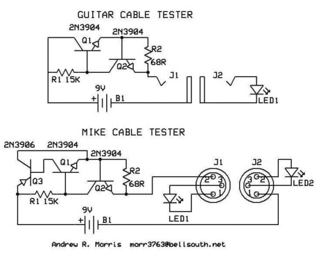
A two-transistor current regulator circuit is used instead of a resistor to maximize battery life.  Any general-purpose silicon 
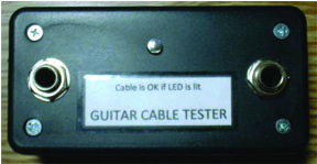
transistor can be used.  The enclosure is Radio Shack P/N 270-1802.  The 1/4 inch phone jacks (Radio Shack P/N 274-252 or Switchcraft P/N 11) are mounted as far apart as possible to make room for the 9-volt battery.  The tip contacts on the jack are rotated inward to prevent the battery from interfering with plug insertion.  The regulator circuits is built on a tiny piece of perfboard tucked into a corner near the J1 connector (the one on the left).  The regulator circuit is built on a tiny piece of perfboard tucked into a corner near the back of the LED to keep them in place.  Foam padding is used to keep the battery from moving inside the box.

The drawing shows both a guitar and a mike version.  Both can be combined in one box if desired, sharing the battery and current regulator.  An additional transistor (Q3) can be added to the current regulator if desired to add about 1.2 volts to the battery headroom.

The guitar cable is OK if LED1 is lit.  For the mike cable, both LED1 and LED2 must be lit.  In the case of the mike cable tester, one XLR connector will be male and the other one female.  High-efficiency LEDs are recommended.

More:  Musical Circuits Testers
Click on Schematic to view PDF

Got Designs?
Please eMail
if you want me to link to and/or post your original design Thanks.


HOME Schematics Index Hobby Corner Dave's Circuits Contact Info
Imagineering Ezine Dave Johnson, P.E. Faraday Touch Switches


 About Us   |  Advertise on DiscoverCircuits.com   |   Report Broken Links  |   Link to DiscoverCircuits.com  |  Privacy Policy

Copyright  January, 1998 - June, 2021     David A. Johnson  All Rights reserved. 

 COPYING any content or graphics to your web site is EXPRESSLY PROHIBITED!