|
 |
Circuits designed by David Johnson, P.E.
Last Updated on:
Monday, December 25, 2017 02:05 PM
List of Dave's Circuit Designs
Text & Graphics Copyright
© David A. Johnson, P. E. -- ALL Rights Reserved..
LINKING to Dave's circuits is permitted but DO NOT COPY content to your WEB SITE
server! |
|
|
|
|
|
|
More
DC-DC Power Supply Classic Linear 5v Supply Using
6.3vac Transformer
(Feb 14, 2009) A classic method for
producing a regulated +5v DC supply is shown below. This circuit consists of an
iron core transformer, a bridge rectifier, a filter capacitor and a voltage regulator.
Many people are tempted to use a very popular 6.3v transformer for this +5v supply but
they will often discover that there just isn’t enough voltage from the transformer to
make the circuit work properly under all but very light load conditions. Higher
transformer voltages will work but at the expense of much more power being dissipated
in the voltage regulator. |
|
| Most
transformers are specified for 120vac inputs. At 110vac, the output of a 6.3vac
transformer may only be 5.8vac. To insure operation under nearly all reasonable
conditions, I will often design a circuit so it would operate properly even with a low
105vac line voltage. Under that condition, the 6.3vac from the transformer may only
be 5.5vac. |
|
|
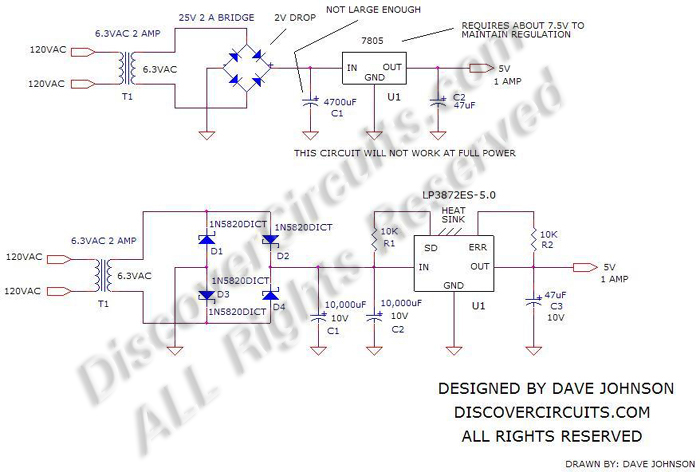
If a typical bridge rectifier and filter
capacitor were used, there
would not be enough peak voltage to insure good regulation.
But, all is not lost. This classic transformer design could still be
used but only if you pick the right parts.
For starters, the conventional bridge rectifier can
be replaced
with four power Schottky diodes. A typical bridge rectifier using standard silicon
diodes would have a voltage drop of about 2 volts, while a Schottky diode bridge would
drop only one volt. Although
this isn’t a lot, it sure helps. Next, the main filter capacitor size
could be increased, to decrease the ripple voltage across it. One
way to calculate the ripple voltage is with the equation:
dv/dt = I/C. dv/dt is the voltage change across the capacitor.
I is the DC load current and C is the capacitance. For 60Hz power lines, the dt
value would be 0.008 seconds. For 50Hz power lines,
use the value of 0.010 seconds. |
|
| So,
if we picked a big 20,000uF capacitor, with a current of 1 Amp, then with a 60Hz
frequency, the ripple voltage (dv) would be about 0.40v and 0.50v for a 50Hz system.
At 105vac the transformer secondary would be 5.5vac. The peak voltage would be 1.41
X 5.5v or 7.7v. Subtract 1 volt for the schottky bridge and 0.40 for the ripple
voltage and you are left with 6.3v DC for the input to voltage regulator. This is
only 1.3v above the desired 5 volts but it should be enough if you use a regulator with a
low input to output voltage drop. I suggest using a LP3872ES-5.0 voltage regulator
from National Semiconductor. This device only needs about 5.3v at the input side to
maintain 5 volts at the output, with a 1 Amp load. In my design, I suggest using a
6.3vac transformer rated at 2 Amps and two big 10,000uF filter capacitors at the bridge
output. Although the voltage drop across the regulator will be small, I would suggest
mounting the regulator on a heat sink, rated for about 5 watts of dissipation. |
|
|
Click
on Drawing Below to view PDF version of Schematic |
|
 |
| |
|
More
DC-DC Power Supply
List of Dave's Circuits
Dave's Circuits with Descriptions
Dave's Circuits by Category
eMail David A. Johnson,
P.E. about this circuit |
|
|