|
 |
Circuits designed by David Johnson,
P.E.
Last Updated on:
Saturday, December 23, 2017 03:21 PM
Master Category List - Dave's Circuits
The contents &
graphics of Discovercircuits.com are copyright protected.
LINKING to Dave's circuits is permitted but DO NOT COPY any files to your WEB
SITE server |
|
|
|
|
|
|
More
Astable Oscillator |
|
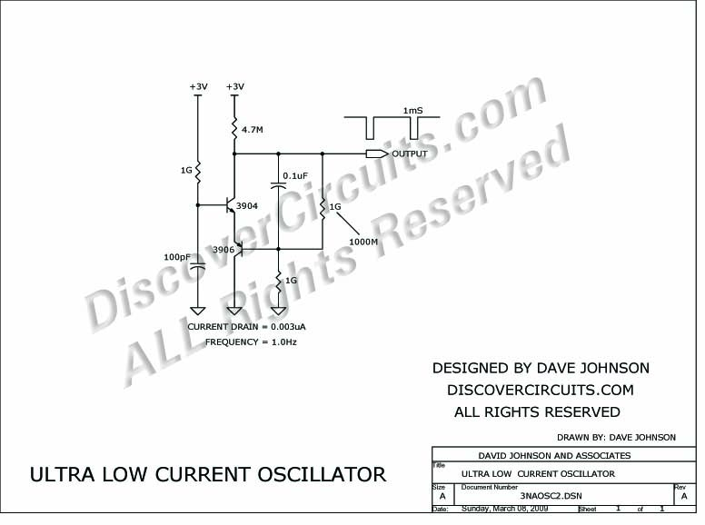
Ultra Low Current Oscillator
(February 17, 2009)
|
| Here is a challenge.
Design an astable oscillator which draws only a few nanoamps of current from a +3v
supply. I gave this some thought and came up with the circuit below. I
used some pretty standard parts except for three surface mounted 1000M resistors I
had on hand. The oscillator frequency measured a low 1Hz frequency and the
average current was a very low 3 nanoamps. If I had some higher resistors
values handy, I think I could have gotten the current down below one nanoamp.
|
|
|
|
The circuit functions like a unijunction transistor relaxation oscillator. The base of
the lower PNP transistor is biased at roughly half supply. As the 100pF capacitor is
charged up through the 1G resistor, the base of the upper NPN transistor reaches a
critical voltage, which begins to forward bias the base-emitter junction of that upper
NPN device and the lower PNP device. The base current causes the collector
current to quickly rise. As current starts to flow in the collector of the upper
NPN part, the collector voltage drops. The 0.1uF cap AC couples this negative going
signal to the base of the lower PNP part. This connection turns that lower part on
harder, causing an avalanche current pulse. The result is the discharge of the
100pF cap. The two transistor circuit then resets and another cycle is started.
How do you measure 3 nanoamps of current? I’ll show a way later, using some
pretty standard parts. |
|
Click on Drawing Below to view PDF version of Schematic |
|
 |
| |
|
|