Electronic Circuits and electronic circuits, electronic schematics plus an extensive resource for hobbyists, inventors and engineers

DiscoverCircuits.com, has 45,000+ electronic circuits, cross-referenced
into 500+ categories.    We have searched the web to help you find quick design ideas.
We make every effort to link to original material posted by the designer. 
Please let us if you would like us to link to or post your design.

HOME Schematics Index Hobby Corner Dave's Circuits Electronic Resources Contact Info
Imagineering Ezine    Discover Solar Energy Dave Johnson & Associates Faraday Touch Switches


Circuits designed by David Johnson, P.E.
Last Updated on: Monday, December 25, 2017 02:08 PM

Master Category List - Dave's Circuits

The contents & graphics of Discovercircuits.com are copyright protected.
LINKING to Dave's circuits is permitted but DO NOT COPY any files to your WEB SITE server

More  Alarm Circuits   Freezer / Frost Alarms
Micro Power Circuits   Temperature Sensors
Temperature Control Circuits      Themocoupler    Thermistor

Freezing Temperature Alarm2
November 5, 2014


The circuit below is designed to activate a beeper alarm, whenever the outside air temperature is below 0 degrees C (32F).  A 9v battery powers the circuit.  The average 9ua current is so low that the battery should last for many years.
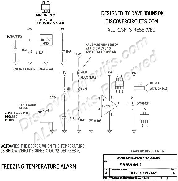
An inexpensive glass diode is used as the temperature sensor.  A small gage unshielded cable can be used to link the temperature sensor to the circuit. The cable length can be up to 20 feet for a small gage wire and longer if you use a heavy gage wire.  The diode and its leads should be covered in some epoxy to form an insulator, with will keep water from coming in contact with the part. The circuit can be housed in a small plastic box.  Some boxes have nice snap out compartments for a 9v battery.

A very low power +5v regulator is used to provide a solid +5v for most of the circuit.  A single low power voltage comparator (LM7215) from National Semiconductor is used to compare the voltages across a bridge network, consisting of the 1N4148 diode and a 1M resistor on one side and a 200K pot, 1.1M resistor and one 82K resistor on the other side.  When the temperature is below freezing, the voltage at the non-inverting (+) input exceeds the inverting input, causing the output of the comparator to swing from zero volts to +5v.  The 5v signal at the gate of the FET then turns on the transistor, which turns on the beeper.

Click on Drawing Below to view PDF version of Schematic


More  Alarm Circuits   Freezer / Frost Alarms
Micro Power Circuits   Temperature Sensors
Temperature Control Circuits      Themocoupler    Thermistor

List of Dave's Circuits
Dave's Circuits with Descriptions
Dave's Circuits by Category

eMail David A. Johnson, P.E. about this circuit


HOME Schematics Index Hobby Corner Dave's Circuits Electronic Resources Contact Info
Imagineering Ezine    Discover Solar Energy Dave Johnson & Associates Faraday Touch Switches


 About Us   |  Advertise on DiscoverCircuits.com   |   Report Broken Links  |    Link to DiscoverCircuits.com  |    Privacy Policy


Copyright  January, 1998 - December, 2017     David A. Johnson & Associates.  All Rights reserved. 


 Linking is ALLOWED but COPYING any content or graphics to your web site is EXPRESSLY PROHIBITED.