Electronic Circuits and electronic circuits, electronic schematics plus an extensive resource for hobbyists, inventors and engineers

DiscoverCircuits.com, has 45,000+ electronic circuits, cross-referenced
into 500+ categories.    We have searched the web to help you find quick design ideas.
We make every effort to link to original material posted by the designer. 
Please let us if you would like us to link to or post your design.

HOME Schematics Index Hobby Corner Dave's Circuits Electronic Resources Contact Info
Imagineering Ezine    Discover Solar Energy Dave Johnson & Associates Faraday Touch Switches


Circuits designed by David Johnson, P.E.
Last Updated on: Monday, December 25, 2017 02:09 PM

List of Dave's Circuit Designs

The contents & graphics of Discovercircuits.com are copyright protected.
LINKING to Dave's circuits is permitted but DO NOT COPY any files to your WEB SITE server

Ultra Low Control Current Optoisolated Power Relay

 (September 23, 2017)
designed by David A. Johnson, P.E.

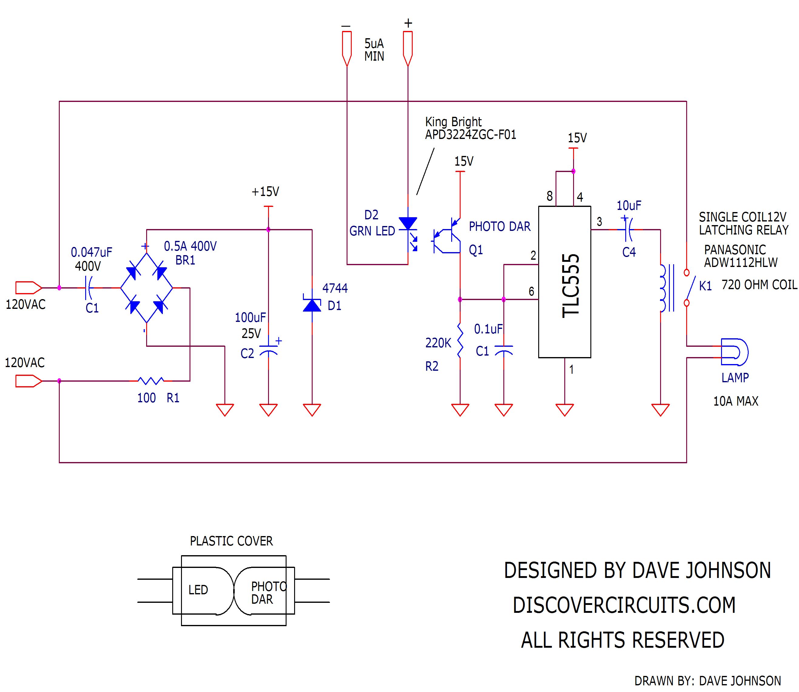
Solid state relays have been used for many decades as a way to control AC power to various loads.  A typical relay demands about 20ma to 50ma of DC current to activate the relay.  Also, a solid state relay does dissipate some power and typically has to be mounted to heat sink when the AC current exceeds 4 amps.  But, there are times, especially with battery powered control devices, when even 20ma is too much current to keep a relay active for a long period of time.  The circuit below uses a mechanical latching relay and a custom opto-isolator to perform the AC switching operation.  The real advantage of the circuit is that it can switch power on and off up to 10 amps of AC current while drawing only 10ua of current.  In fact, I have tested the circuit using just 5ua of control current.


The circuit uses a classic capacitor “voltage dropper” to capture a bit of power from the AC power line and store some energy in a capacitor.  The energy is then used to activate a latching relay.  The relay only needs short 20ms pulses to open or close the relay contacts.  So, the average power needed to hold the relay state is very low.

I use a do-it-yourself isolator drive circuit.  The circuit points the end of an efficient green LED toward a photo-darlington transistor.  Only a tiny bit of light is needed from the LED to saturate the photo-darlington light sensor.  I use a 555 timer to monitor the on/off state of the light sensor, which appears as a voltage across R2.  When the voltage reaches about 10v, the 555 timer output changes state and unlatches the relay.  The capacitor C4 provides the needed polarity reversal and applies short current pulses to the relay coil.  Be sure to select the relay coil polarity so the relay contacts latch closed, when current is fed to the LED side of the opto-isolator assembly.

Single Coil 12v Latching Relay, 10A Rating
 
Click on Drawing Below to view PDF version of Schematic

List of Dave's Circuits
Dave's Circuits with Descriptions
Dave's Circuits by Category


eMail David A. Johnson, P.E. about this circuit


HOME Schematics Index Hobby Corner Dave's Circuits Electronic Resources Contact Info
Imagineering Ezine    Discover Solar Energy Dave Johnson & Associates Faraday Touch Switches


 About Us   |  Advertise on DiscoverCircuits.com   |   Report Broken Links  |    Link to DiscoverCircuits.com  |    Privacy Policy


Copyright  January, 1998 - December, 2017     David A. Johnson & Associates.  All Rights reserved. 


 Linking is ALLOWED but COPYING any content or graphics to your web site is EXPRESSLY PROHIBITED.