|
Circuits designed by David Johnson, P.E.
Last Updated on:
Friday, December 29, 2017 02:53 AM
List of Dave's Circuit Designs
The contents & graphics of
Discovercircuits.com are copyright protected.
LINKING to Dave's circuits is permitted but DO NOT COPY any files to your WEB
SITE server |
 |
|
|
|
|
DC CURRENT INDICATOR #4
December 15, 2008
|
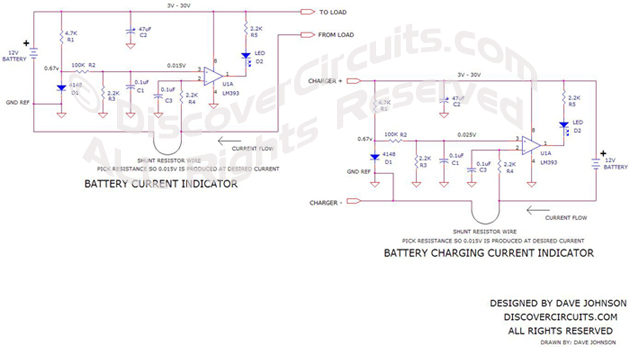
| The circuit below uses some
common components to turn on an LED whenever DC current above a certain level is detected.
The circuit uses a very popular LM393 dual voltage comparator from National Semiconductor
and a common 1N4148 signal diode. The diode acts as a crude 0.7v voltage reference.
Only one of the comparators inside the 8 pin package is used. A pair of resistors
across the diode forms a voltage divider, which produce a reference voltage of about
0.015v. The circuit compares this reference voltage to a voltage produced across a current
shunt resistor. A section of wire already in place can be used as the current shunt.
The circuit can be used to indicate current drawn from a battery and routed to a load or
current from a battery charger to the battery. Both circuits are shown on the drawing.
The circuit shows components for a 12v system but it will work well using any DC supply
from 3v to 30v. |
| The circuit is
sensitive enough that it can indicate fairly small currents through a section of thick
wire. As an example, an 18ga wire only 24 inches long will have a resistance
of about 0.013 ohms. The needed 0.015 volts will be generated with a current flow of
about 1.2 Amps. If more sensitivity is needed, a longer section of wire can be used as a
shunt resistor. |
| Use Ohm’s Law to
calculate the resistance needed. Ohm’s Law equation is: E = RI, where R is the
resistance in ohms, E is the voltage developed across the resistance in volts and I is the
current flowing through the resistor in Amps. If we set E at 0.015 volts and R at
0.0012 ohms, then I = 1.2 Amps. |
Here is one example how this circuit might be used.
Suppose you have a large 12v battery, which supplies current to various loads inside a
recreational vehicle (RV). You noticed that a 10ga wire 10 feet long connects the
battery negative terminal to a junction box. You look up the resistance of the 10ga
wire from a chart and out that the typical resistance is about 0.001 ohms per foot.
Therefore, if you used the battery negative terminal as one point of reference and the
connection in the junction box as another point, then the resistance should be about 0.01
ohms. If the current indicator circuit were connected between those two points, then
the circuit should switch on the LED whenever current exceeding 1.5 Amps is drawn from the
battery.
|
In another example, suppose you have a
battery changer connected to a 12v lead acid battery. The charger uses a pair of
18ga wires 12 feet long. The resistance of 18ga wire is about 0.0064 ohms per
foot, so the resistance of one of the 12 foot wires should be about 0.077 ohms.
Using the current indicator circuit and using the two ends of the cable as reference
points, the LED should turn on whenever the charging current exceeds 0.20 Amps.
The indicator light should turn off when the battery is fully charged.
|
|
|
| Here is a
link to a Table
for Copper Wire |
|
Click on Drawing Below to view PDF version of Schematic |
|
 |