|
 |
Circuits designed by David Johnson,
P.E.
Last Updated on:
Saturday, December 23, 2017 03:21 PM
Master Category List - Dave's Circuits
The contents &
graphics of Discovercircuits.com are copyright protected.
LINKING to Dave's circuits is permitted but DO NOT COPY any files to your WEB
SITE server |
|
|
|
|
More
Digital
Control
Motor Control
|
|
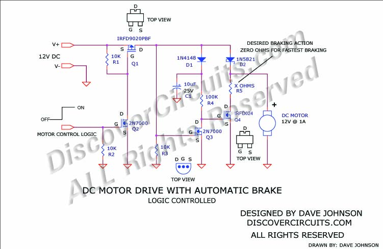
Logic Controlled 12v DC Motor
with Automatic Brake
February 18, 2010
|
| There are times when
you would like to control a DC motor using a simple +5v logic swing signal.
The circuit below performs this feat and also includes an automatic motor braking
circuit. When the input logic signal swings from 0v to +5v, the n-channel
MOSFET Q2 turns on, which turns on the p-channel MOSFET Q1. Current flows
into the motor through the schottky diode D2. When the control logic swings
back 0v, Q1 turns off. This activates the braking action of Q4, which
applies a short across the motor. The sudden stop is often desired in some
motor controlled systems. |
|
|
|
|
Click on Drawing Below to view PDF version of Schematic |
|
 |
|
|
|
|
|
|