|
 |
Circuits designed by David Johnson, P.E.
Last Updated on:
Monday, December 25, 2017 02:09 PM
List of Dave's Circuit Designs
The contents & graphics
of Discovercircuits.com are copyright protected.
LINKING to Dave's circuits is permitted but DO NOT COPY any files to your WEB
SITE server |
|
|
|
|
|
|
|
More
Super Capacitor Circuits
Ultracapacitor Voltage Limiting
Circuit
Supercapacitors are working their way into more and more applications where electrical
energy needs to be stored. These robust devices can be charged and discharged
1000s of times and will typically outlast a battery. Many supercap manufacturers
claim a life span of 10 years or more. A supercapacitor is often chosen to
supply power to low current load for many hours at a time, recharged by a solar panel.
|
| All supercapacitors have a maximum
voltage rating. When charging these devices, that voltage should not be
exceeded. Doing so can damage the device. In many applications several
capacitors are wired in series, to produce a capacitor bank with a higher voltage.
But even if the proper charging voltage is used the weakest device in the string
will charge up first.
Without a circuit to limit the voltage across each
part, the weakest part in the series string will be overcharged as the rest of the
parts in the string finish their charge. The circuit below solves this over-voltage
problem by balancing the string with a voltage limiting circuit across each
capacitor. |
 |
|
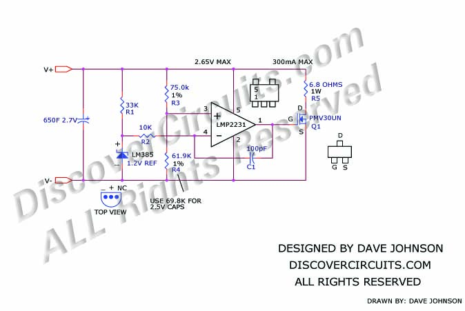
| The
circuit diverts charging current around each part, when the voltage reaches a critical
point. The circuit is really a classic 2.65v shunt type voltage regulator. It
takes advantage of a LMP2231 low voltage op Amp from National Semiconductor, a low current
LM385 voltage reference, also from National, and a PMV30UN n-channel FET from NXP
Semiconductors, which has a low gate-source threshold voltage. |
| In the
application shown, three 310 farad supercapacitors from Maxwell, part number BCAP0310, are
wired in series, to form an energy storage bank. The voltage from the bank is
connected to a Seiko low voltage drop 3v voltage regulator. Power to charge the
supercapacitor bank comes from a 3 watt 9v solar panel, with a short circuit current of
about 300ma. The three voltage limiting circuits keep the voltage across each
capacitor at 2.65v for a total of 7.95v for the capacitor bank, when fully charged.
|
| A
solar panel will typically produce about 5% of full power when the sky is heavily
overcast. That means that a minimum of 15ma could be expected from the solar panel
during about 8 hours of daylight. If the 3v DC output is restricted to an average of
5ma of current, then there would be enough charge in the capacitor for about 24 hours of
complete darkness. Up to 100ma of peak current could be drawn from the 3v supply if
needed for such applications as a RF transmitter. Energy drawn from the capacitor
bank during night operation is restored by the solar panel. |
|
|
Click
on Drawing Below to view PDF version of Schematic |
|
 |
|
|
|