Electronic Circuits and electronic circuits, electronic schematics plus an extensive resource for hobbyists, inventors and engineers

DiscoverCircuits.com, has 45,000+ electronic circuits, cross-referenced into 500+ categories.
We have searched the web to help you find quick solutions & design ideas.

Got Designs?
Please eMail
if you want me to link to and/or post your original design
NOTE:  We make every effort to link to original material posted by the designer. 
Please contact us if our link is not to your site!  Thanks.

DiscoverCircuits.com -- Hobby Corner
Last Updated on: Tuesday, June 01, 2021 03:06 PM

Hobby Circuits List

The contents & graphics of Discovercircuits.com are copyright protected.
LINK to Dave's circuit, but DO NOT COPY any files to your WEB SITE server

More  Beeper Circuits

24V DC Powered Beeper with 4 Separate Inputs
May 17, 2007
designed by David A. Johnson, P.E.

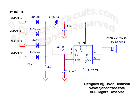
24v DC is a very popular voltage used in industrial settings.  This hobby circuit below was designed to accept four different 24v DC alarm input signals, which are then used to drive a single low power beeper. 
The beeper is a magnetic type with its own oscillator/driver.  The four diodes form an “OR” gate so any one of the four inputs will cause the beeper to make noise.  A CMOS version of the popular 555 timer is used to strobe the beeper on and off at about 1Hz.

Click on Circuit Below to view PDF of Schematic


24V DC Powered Beeper with 4 Separate Inputs, designed

 by David Johnson, May 17, 2007


Hobby Circuits List
eMail David A. Johnson, P.E. about this circuit


HOME Schematics Index Hobby Corner Dave's Circuits Contact Info
Imagineering Ezine Dave Johnson & Associates Faraday Touch Switches


 About Us   |  Advertise on DiscoverCircuits.com   |   Report Broken Links  |    Link to DiscoverCircuits.com  |    Privacy Policy

Copyright  January, 1998 - June, 2021     David A. Johnson  All Rights reserved. 
 Linking is ALLOWED but COPYING any content or graphics to your web site is EXPRESSLY PROHIBITED.