|
 |
DiscoverCircuits.com -- Hobby Corner
Last Updated on:
Tuesday, June 01, 2021 03:06 PM
Hobby Circuits List
The contents &
graphics of Discovercircuits.com are copyright protected.
LINK to Dave's circuit, but DO NOT COPY any files to your WEB
SITE server |
|
|
|
|
More
Timers |
|
Motorized Duck Decoy Timer
I received an
email from a duck hunter. He uses some motorized decoys to lure ducks into his
line of fire. However, the battery powered decoys only have an on/off switch
so once turned on; the decoy flaps its wings or paddles around continuously.
The hunter wanted a more realistic motion, which would power the motor for say 10
seconds, then stop for another 10 seconds before starting up again. The simple
circuit below should work well for his application. |
|
|
|
The circuit uses a classic CMOS
version of the 555 timer as a low frequency oscillator. Using a variable resistor,
the flapping time can be adjusted from about 2 seconds to about 50 seconds. An
n-channel FET with a low gate-source threshold is needed in this circuit since the
circuit is powered by two big alkaline D cells, producing 3 volts. I provided a
couple different FET part numbers, which are available from
www.digikey.com. The circuit is wired in between the on/off switch and the two
motors. If surface mounted parts are used, the circuit should be about the size of
a postage stamp. I would recommend coating the board with some conformal material
to insure water does not short out the circuit. |
 |
 |
| "Wonder Duck" |
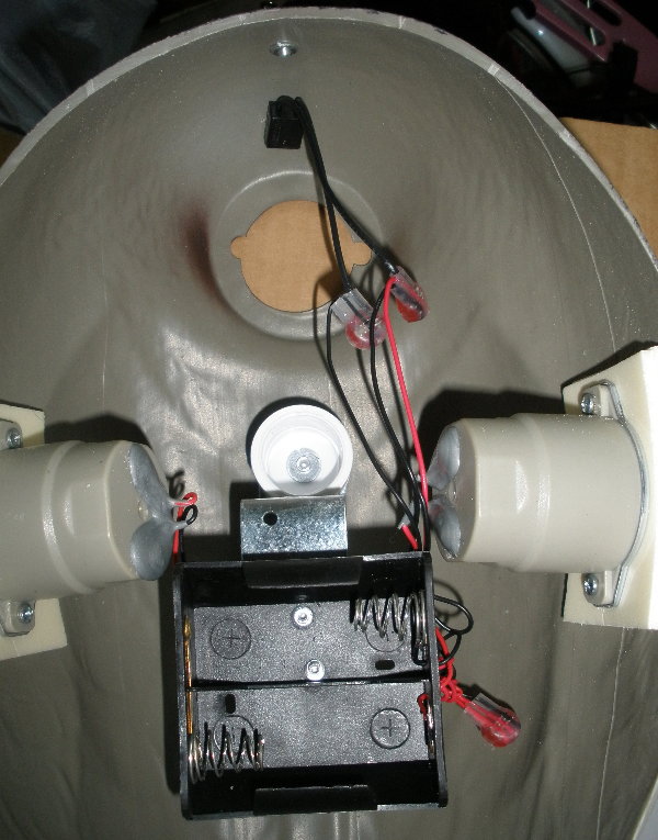
Here is a shot of the inside of the decoy assembly. |
|
|
Click below for a
video of the duck in action.
http://www.youtube.com/watch?v=bMgRRtt9d10&feature=related
The decoys are made
by Wonderduck and may be purchased at www.wonderduck.com. |
|
Click on Circuit Below to view PDF of Schematic |
|
 |
|
|
|
|