|
 |
DiscoverCircuits.com -- Hobby Corner
Last Updated on:
Friday, December 29, 2017 05:52 AM
Hobby Circuits List
The contents &
graphics of Discovercircuits.com are copyright protected.
LINKING to Dave's circuits is permitted but DO NOT COPY any files to your WEB
SITE server |
|
|
|
|
More
Beeper & Buzzer Circuits
Doorbell Circuits |
|
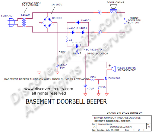
BASEMENT DOORBELL BEEPER |
If you can’t hear your front doorbell when you are in your basement, this circuit
might work for you. Whenever the front doorbell button is pressed, the hobby
circuit will activate a loud beeper positioned in the basement. This circuit takes
advantage of the fact that in many homes, the 24vac power transformer used to power
the doorbell is located near the furnace in the basement. A box containing the
electronic circuit could be mounted next to the transformer. |
|
|
|
|
A small bridge rectifier converts the 24vac into DC.
The 100uF capacitor filters the pulsating DC from the bridge to form about 30v DC.
Three diodes are wired in series with the door chime. Whenever the front door
pushbutton is pressed, the door chime sounds. AC current drawn b the chime is
routed through the three diodes shown. The two diodes in series forms a 2 volt
voltage source, which is connected to an inexpensive opto-isolator. The 2
volts across the two diodes is sufficient to turn on the opto-isolator circuit,
which routes DC to the gate of the ZVN4206 FET. When the doorbell chime
sounds, the FET turns on a piezoelectric beeper, drawing power from the 30 DC
supply. Make sure the beeper you use can handle the higher 30v voltage |
|
|
Click on Drawing Below to view PDF version of Schematic |
|
 |
|
|
|
More
Beeper & Buzzer Circuits
Doorbell Circuits
Hobby Circuits List
eMail David A.
Johnson, P.E. about this circuit |
|
|