|
DiscoverCircuits.com -- Hobby Corner
Last Updated on:
Tuesday, June 01, 2021 03:06 PM
Hobby Circuits List
The contents &
graphics of Discovercircuits.com are copyright protected.
LINK to Dave's circuit, but DO NOT COPY any files to your WEB
SITE server |
 |
|
|
|
|
|
|
More
Battery Tester Circuits |
|
Small Battery
Capacity Tester
Sept 7, 2008
designed
by David A. Johnson, P.E. |
| I have a client who uses
a lot of batteries. His sells a device which is powered by a 3v lithium coin
cell and he sells thousands of them. It seems that many of the batteries he has been
importing from China have a milliamp-hour capacity which is much lower than quality
batteries from US or Japan manufacturers. In many cases the capacity was less
than half of what it was suppose to be. |
|
| His
measurement technique was rather crude. He would just insert one of the batteries
into his product and time how long it powered it before dying. Many fresh Chinese
batteries lasted only half as long as batteries from Energizer or Panasonic. But,
his test can take a long time. In one of his products it takes a full month to
complete a test. He wanted a more accurate measuring technique and he also wanted one
that would tell him the capacity of the battery in a much shorter period of time.
I proposed an automatic tester which could give him some test results overnight. With
the device I proposed, he could test a few sample batteries against some standard
quality batteries. If they tested OK, he could then approve them for his product.
|
|
The
only truly accurate way to measure the current capacity of a battery is by
connecting the battery to a constant current load and measure how long the battery
can sustain that current before its voltage drops below a recommended “cutoff”
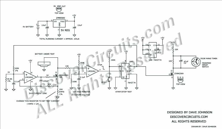
point. The circuit below is designed
to do this type of test.
The
circuit is powered by a +5v source. A low power 5v regulator powers the circuit from
a 9v battery. The left side of the circuit forms a constant current sinking circuit.
A 1v reference voltage is produced with a voltage divider. The FET transistor
is fed the exact amount of voltage to maintain this 1 volt drop across the 200 ohm
resistor. Thus, battery current is drawn at 5 milliamps for the component values
chosen. By changing the 200 ohm resistor to some other value, other test currents
can be produced. The test current is: 1/R. |
|
|
|
The middle section of the circuit is
configured as a voltage comparator. With the component values chosen, the
comparator will change state when the battery voltage drops below 2 volts. |
|
A flip/flop is used to start and
automatically stop the test. When the pushbutton switch is pressed the flip/flop
starts the test. When the battery voltage drops below the cutoff voltage, the
flip/flop changes state and stops the test. |
|
To
measure the elapsed test time, I use a modified wrist watch. The battery has been
removed and two wires have been connected to the watch’s battery holder. The watch
starts operating when the test is running and stops after the test. You set the
watch at 12:00 midnight to start a test. At the end of the test, the watch retains
the elapsed time. If a wrist watch containing a day and date display is used, the
test can last as long as 31 days. |
|
The tester can test almost any small
battery, from tiny hearing aid cells to larger coin cells. However, the maximum load
test current should be kept below 100ma with parts indicated. With some
modifications and component changes, the same technique could be scaled up to test much
larger batteries. |
|
Keep in mind that due to the internal
resistance of many batteries, the elapsed test time for a shot overnight test may be
much shorter than expected. As an example, a quality lithium coin cell might have
a specified capacity of 220ma-hours but will reach the 2v cutoff voltage in only about
20 hours. This would lead one to believe that the capacity would only be 20 x 5 =
100 milliamp-hours. However, when the test is done at 100 microamps, the battery
may last three months. The concept is to compare the test result times between quality
batteries to those of unknown origins. |
|
|
Click on Circuit Below to view PDF of Schematic |
|
 |
|
|
|
More
Battery Tester Circuits
Hobby Circuits List
eMail David A.
Johnson, P.E. about this circuit |