|
DiscoverCircuits.com -- Hobby Corner
Last Updated on:
Tuesday, June 01, 2021 03:06 PM
Hobby Circuits List
The contents &
graphics of Discovercircuits.com are copyright protected.
LINK to Dave's circuit, but DO NOT COPY any files to your WEB
SITE server |
 |
|
|
|
|
|
|
More
Battery Charger Circuits |
|
CANDLE POWER
designed
by David Johnson, P.E. |
| I was challenged by a
Discover Circuits visitor a while back. He wanted to know how to generate
some electricity from the heat produced by a common candle. He further added
that he didn’t want the heat to electricity converter to use any moving parts.
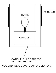
That meant a steam or Stirling engine would be ruled out. I put my thinking cap
on and came up with two different methods to produce a very modest amount of
electrical power. |
|
|
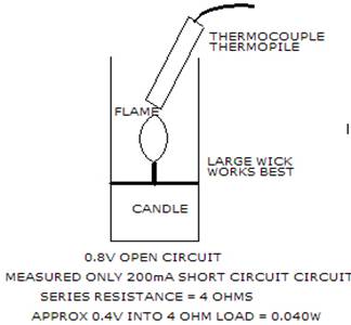
I first purchased a common “millivolt” thermopile
voltage generator from an eBay auction. These are often used to monitor the
pilot light of a gas fireplace. The typical unit generates about 0.8v open
circuit. As the illustration shows below, with the thermopile placed in a good
hot candle flame, I measured an open circuit voltage of about 0.8v and a short
circuit current of 200ma. The DC resistance of the device measured 4 ohms.
With a quality DC motor attached to the device, the voltage dropped from 0.8v to
0.4v but the motor spun nicely. With a 4 ohm series resistance, the peak
power for this device would therefore occur when the load resistance equaled the
source resistance or about 4 ohms. Under these conditions the thermopile
would pump about 100ma into a 4 ohm load or about 40mw of power.
|
|
If an 85% efficient DC to DC converter were used to
boost the voltage to a higher level, this would be enough to light a 2 volt red led at
a current level of 16ma. Such a current would be enough to produce a nice output
from the LED. If the candle power circuit were used to charge a 1 Amp-hour
lithium ion cell phone battery, it might take about 5 days to charge it up.
Although this device works, it clearly would not be practical for anything but a way
to power a pilot light indictor lamp or some other low power load. |
|
For a short movie showing a candle powered motor,
double click here. (download of movie is slow,
please be patient) Some time later, I will post
a circuit which could take the low voltage from the thermopile and boost it to a more
useful voltage. |
|
|
|
|
|
More Battery Charger
Circuits
Hobby Circuits List
eMail David A.
Johnson, P.E. about this circuit |
|
|