|
DiscoverCircuits.com -- Hobby Corner
Last Updated on:
Tuesday, June 01, 2021 03:06 PM
Hobby Circuits List
The contents &
graphics of Discovercircuits.com are copyright protected.
LINK to Dave's circuit, but DO NOT COPY any files to your WEB
SITE server |
 |
|
|
|
|
|
|
More
Model Train Circuits;
LED Circuits; Flashing
Lights; Models |
|
HO Train Lighthouse Flasher
Revisited
December 24, 2012
designed
by David A. Johnson, P.E. |
| HO train sets
often have authentic looking scale model homes and buildings.
A while back someone asked me to design a flashing LED light,
which he could mount inside a model lighthouse and have it
operate so it would appear to rotate and flash. I designed
a working circuit but I was never pleased with the results.
I’m still not 100% pleased but the revised circuit below seems
to operate a bit better than the older circuit.
|
|
The
circuit below can be mounted inside a model lighthouse and powered by 4 AA alkaline
cells or a 5v to 6v supply. The circuit drives a single LED lamp with a pulse
width modulation (PWM) ramping signal. The ramp simulates the rotating light from
a lighthouse beacon. The circuit uses two CMOS
versions of the 555 timer and a
common LM393 dual voltage comparator. The triangle signals generated by the two
timers converge at the inputs to the comparator. The slow 0.14 Hz lower oscillator
makes a complete cycle in about 7 or 8 seconds. The second oscillator runs at
about 10KHz. The PWM output of the LM393 is connected to a FET switch. The PWM
signal at the FET gate causes the average light intensity of the LED to swing from about
5% to 95%, with R4 limiting the current to about 4 milliamps. At the peak of the
PWM signal, a pulse from the lower 555 timer is routed to a second FET switch. The
signal applies a 50ms pulse to the LED through a second resistor R5. The result is
a LED light, which gradually grows brighter, then flashes even brighter before dimming
down again. This produces a light, which somewhat simulates a rotating lighthouse light
although I think a llogarithmic waveform would produce a better intensity ramp than a
triangle waveform. Perhaps that feature could be added later.
 |
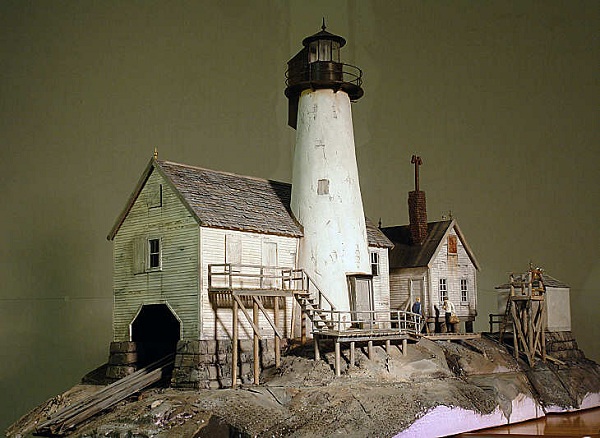 |
| HO Train Model
Lighthouse |
HO Train Model
Lighthouse |
|
|
|
Click on Circuit Below to view PDF of Schematic |
|
 |
|
|
|
|
|
|