|
DiscoverCircuits.com -- Hobby Corner
Last Updated on:
Tuesday, June 01, 2021 03:06 PM
Hobby Circuits List
The contents &
graphics of Discovercircuits.com are copyright protected.
LINK to Dave's circuit, but DO NOT COPY any files to your WEB
SITE server |
 |
|
|
|
|
|
|
More Voltage to
Frequency Converters
Freespace Communications
VCO Circuits
Light Sensor Circuits |
|
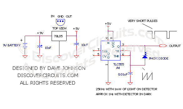
Light to Frequency Converter
designed
by David A. Johnson, P.E. |
| This circuit uses a CMOS
version of the classic 555 timer, to form a light intensity to frequency converter.
A small PIN photo diode is used as the light detector. The pulses produced are
short, so in some applications you may want to stretch them or feed them through a
flip/flop to produce a square wave signal. Although the circuit shown is
designed
for a 5v supply, it could operate from almost any voltage from 3v to 15v. |
|
| The
555 timer circuit is configured as a free running oscillator. When a PIN
photodiode is reversed biased, it leaks current proportional to the light intensity
hitting lt. The photodiode leakage current charges the 0.01uF capacitor.
When the voltage of the capacitor reaches about 2/3 of the supply voltage, the pin 3
output of the 555 timer swings low. This state quickly discharges the capacitor
through the photo diode, until the capacitor voltage is less than 1/3 of the supply
voltage. This causes the pin 3 output of the 555 to swing high again, for another
charge cycle. With the component value chosen, the frequency of the oscillator
will range from about 1Hz in total darkness to about 25KHz in sunlight. Other
frequencies are possible by changing the value of the 0.01uF capacitor. |
|
|
Click on Circuit Below to view PDF of Schematic |
|
 |
|
|
|
|
|
|