|
DiscoverCircuits.com -- Hobby Corner
Last Updated on:
Wednesday, June 02, 2021 04:27 AM
Hobby Circuits List
The contents & graphics of Discovercircuits.com are copyright protected.
LINK to Dave's circuit, but DO NOT COPY any files to your WEB SITE server |
 |
|
|
|
|
|
|
Poor Man's Timer
Aug 24, 2008
designed
by David A. Johnson, P.E. |
|
Often during testing of
certain equipment and components, you would like to keep track
of the elapsed time in hours, minutes and seconds. There are
some nice commercial digital timers and counters available for
just this sort of application. However, although it may not
be as accurate, there is a cheaper way to go. I�m sure many
of you have some old wrist watches or battery powered dial
faced alarm clocks collecting dust in some drawer. With just
a bit of effort you can turn these into value pieces of test
equipment. You must use the analog clocks and watches with
dial faces and not digital types, since the analog devices
retain the elapsed time information, even after the power is
interrupted. |
|
|
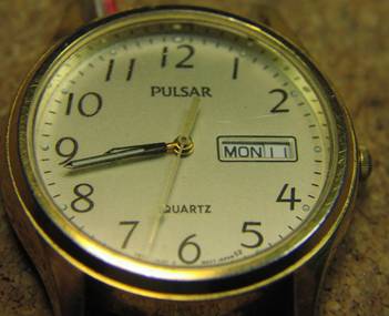
With a wrist watch that has a day/date feature, you can time things up to 31 days, to an accuracy of a few seconds.
Most wrist watches
are powered by 1.5v button cells while many dial face alarm clocks are
powered by 1.5v AA or AAA cells. These timing devices draw very little
current and can easily be wired into an electronic circuit. The circuit
might be connected to a microprocessor or some sensing device. When
power is applied to the clock, the elapsed time is recorded. When power
is turned off, the elapsed time information is retained.
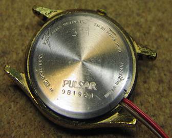
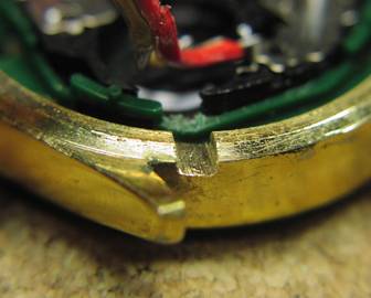
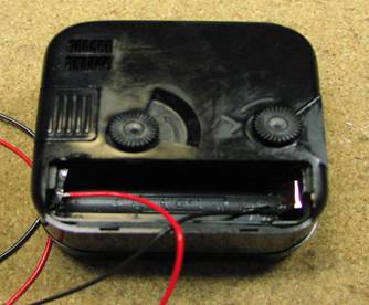
To convert these
devices into a timer, first open the back of the watch or the battery
compartment of the clock. Remove the battery. File a 1/8 inch wide by
1/16 inch deep notch into the metal of the watch case or the plastic of
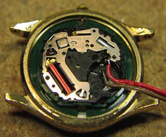
the battery compartment lid. Next, solder two wires onto the battery
contacts.
|
|
|
|
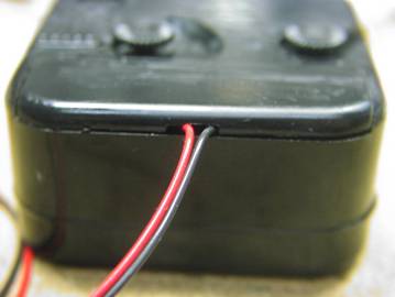
Use a thin red wire, about 12 inches long, for the positive side and a darker color, such as black, for the negative terminal. If you have difficulty applying solder the clock�s battery contacts, you can first press some adhesive copper tape onto the contacts, then solder the wires onto the tape. Route the two wires through the notch. Then close up the back plate or compartment. That is it. You are now are ready to time something.
|
|
|
|
Watch Face |
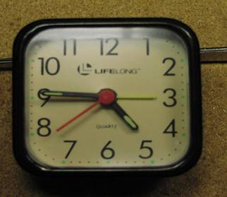
Clock Face |
|
 |
 |
|
|
|
Watch Back
|
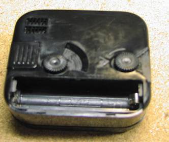
Clock Back,
Battery Removed |
|
 |
 |
|
|
|
Notch Filed
in Watch Case |
Wires
Soldered to Battery Contacts |
 |
 |
|
|
|
Wires
Soldered to Battery Contacts |
Wires Routed
Through Notch |
 |
 |
|
|
|
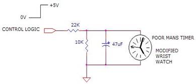
A simple voltage
divider circuit can be used to convert the +5v logic signal from a
computer or a logic device into a 1.5v signal, to power the clock. I
suggest a capacitor be included, to provide the needed peak current
pulse needed by the clock�s solenoid. |
|
|
|
What might you use
this thing for? One application might be to time how long a door
remains open during the day or week. Maybe you could use it to time how
long a battery can power a device or maybe how many hours a computer is
being used per month. I will later show how this simple device can be
used to measure the milliamp-hour capacity of a button or coin cell
battery. |
|
|
|
Click on Circuit Below to view PDF of Schematic |
|
 |
|
|
|
Hobby Circuits List
eMail David A.
Johnson, P.E. about this circuit |
|
|