|
DiscoverCircuits.com -- Hobby Corner
Last Updated on:
Tuesday, April 01, 2014 04:34 AM
Hobby Circuits'
Category List
The contents &
graphics of Discovercircuits.com are copyright protected.
LINKING to Dave's circuits is permitted but DO NOT COPY any files to your WEB
SITE server |
 |
|
|
|
|
|
|
More
Timer Circuits |
|
Poor Man’s
Digital Counter Using Pedometer
Aug 17, 2008
designed by David A. Johnson, P.E. |
| There
are many occasions when you may want to count something electronically.
Perhaps it is car traffic on a street or items moving down an assembly line.
It might be the number of times a machine is activated or maybe you want to count
the number of people entering doorway. Commercial counting modules do exist
but if you want to use something cheaper, you can modify a pedometer to do much the
same thing. |
|
|
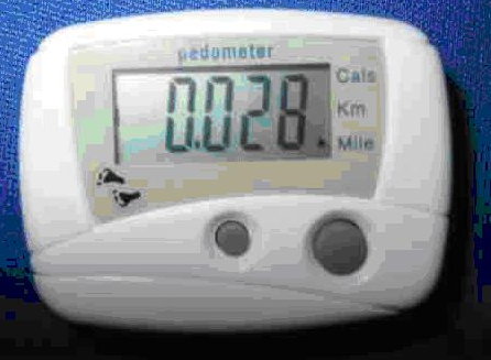
You can usually find inexpensive digital pedometers near the checkout
stand in many stores. I have seen these things in drug stores, food stores and
even shoe stores. They cost about $5 and usually look like the models shown
below. They are clipped onto a belt and have a swinging pendulum switch
inside, which makes contact with each step taken. There usually is a
pushbutton switch, to set the mode of operation and a second switch to reset the
count to zero. Some models just have a single reset button and only count steps.
Most have at least 5 digits for a maximum count of 99,999. They are usually powered
by a single small 1.5v alkaline button cell. |
[H-Corner/ads/i-HC-boombox_adsense.htm]
|
|
|
It is fairly easy to open up one of
these things and replace the mechanical pendulum switch with either an external
electronic transistor switch, controlled by some logic signal, or a simple mechanical
switch, such as a pushbutton. With a simple modification, this device can count
something other than footsteps. Since the device was originally used to count
footsteps, the electronics of the module restricts the counting rate about 3 counts per
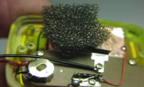
second. If you are going to use this thing often, I would suggest removing the
small 1.5 volt button battery and replace it with a larger cell. A #357 silver
oxide cell should keep the thing operating for years. I used a couple small wires
and some copper foil adhesive tape, to mount the large cell inside the case. A bit
of foam rubber will hold the cell in place, when the case back is reinstalled. |
|
|
|
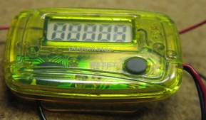
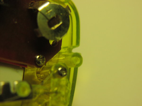
To start the modification process,
first remove the back of the assembly. Usually two small screws hold the back on.
With the back removed, note the termination metal plate for the thin spring wire
attached to the pendulum weight. Also note the contact pad, which the pendulum
strikes, with each footstep |
|
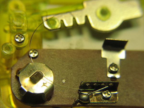
Next, remove the whole pendulum
assembly, including the thin spring wire. Usually only one screw holds the
assembly together.
Next, file a groove about 1/8” wide
and 1/16” deep on the edge of the plastic case, next to the silver battery holder.
The groove will be used to route two thin insulated wires through the plastic case.
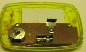
Next, solder a small gauge red wire
to the battery case and a similar black wire to the pendulum contact metal tab.
The two wires can be almost any length. These wires will be routed to either an
external mechanical switch or an electronic transistor switch. |
|
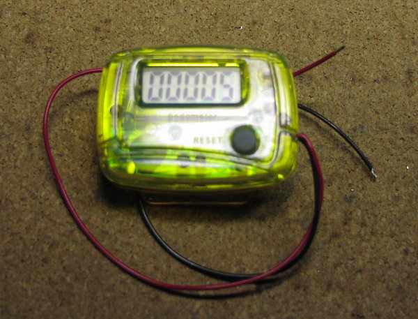
After soldering the two wires, you can
then reinstall the back plastic case to the main assembly. Test the counting unit
by briefly touching the ends of red and black wires together. The count should advance
each time the stripped wire ends touch. |
 |
 |
|
Pedometer Unit to Be Modified |
Pedometer Back Removed,
Note Pendulum Weight on Top |
|
 |
 |
|
Pendulum Assembly Removed |
Slot Cut into Case for Two Switch Wires |
|
 |
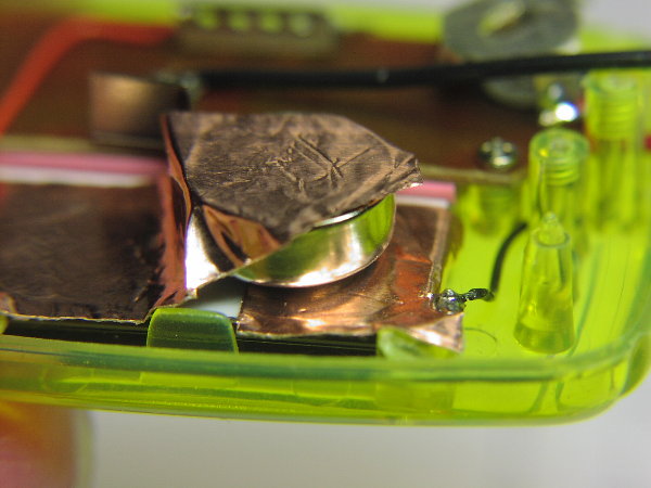 |
Red and Black Wires Soldered to Switch Contacts
Routed Through Slotted Hole |
#357 Battery Cell Installed Using Copper Foil |
|
 |
|
Completed Counter Assembly |
|
|
|
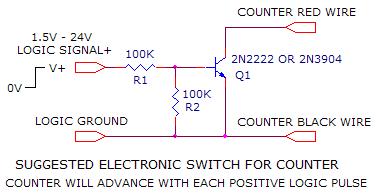
Click on Drawing Below to view PDF version of Schematic |
|
 |
|
|
|
More
Timer Circuits
Hobby Circuits'
Category List
eMail David A.
Johnson, P.E. about this circuit |