|
 |
DiscoverCircuits.com -- Hobby Corner
Last Updated on:
Tuesday, June 01, 2021 03:06 PM
Hobby Circuits List
The contents &
graphics of Discovercircuits.com are copyright protected.
LINK to Dave's circuit, but DO NOT COPY any files to your WEB
SITE server |
|
|
|
|
|
|
More
Alarm Circuits |
|
Earthquake Alarm Circuit
designed
by David Johnson, P.E. |
| Geophones are dandy
motion sensors. They are metal cans containing a powerful magnet, suspended
with springs inside a coil of wire. The magnet functions as a floating mass.
The slightest vertical motion of the device causes the coil to move relative to the
magnet. |
|
|
This induces a small voltage in the wire coil.
These devices have been used for decades by oil and gas companies to conduct surveys
of underground rock and strata, using induced seismic shocks. Although millions of
them have been manufactured over the years they are often hard to find. You
can make your own geophone by suspending a strong magnet with a rubber band, so it
hangs inside a coil of wire containing several hundred turns. Any vertical movement
will produce a detectable voltage in the coil. To reduce false signals produced by
air movements, I suggest that the assembly be housed inside a pipe or some other
container. |
|
|
| The hobby circuit below shows how
this do-it-yourself geophone can be used as an early warning earthquake alarm.
The electronic circuit uses a low power dual op Amp from National Semiconductor.
The weak voltage from the coil is first Amplified by the left side circuit.
That signal is fed to voltage comparator. The output of the comparator is
routed through a filter network then to a n-channel FET switch. The switch
can be used directly to turn on a beeper or it could be connected to a computer
system. I included a LED light as a visual indicator. The LED will
turn on whenever the circuit detects motion. With the components shown, the
overall sensitivity is less than one millivolt peak to peak at the coil. By
decreasing the value of R5, you can decrease the sensitivity so any desired level. |
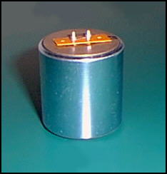 |
| |
Commercial Geophone |
|
|
|
Click on Circuit Below to view PDF of Schematic |
|

|
|
|
|
More
Alarm Circuits
Hobby Circuits List
eMail David A.
Johnson, P.E. about this circuit |