|
 |
DiscoverCircuits.com -- Hobby Corner
Last Updated on:
Friday, December 29, 2017 05:52 AM
Hobby Circuits List
The contents &
graphics of Discovercircuits.com are copyright protected.
LINKING to Dave's circuits is permitted but DO NOT COPY any files to your WEB
SITE server |
|
|
|
|
More
Driver Circuits
LEDs White LEDs |
|
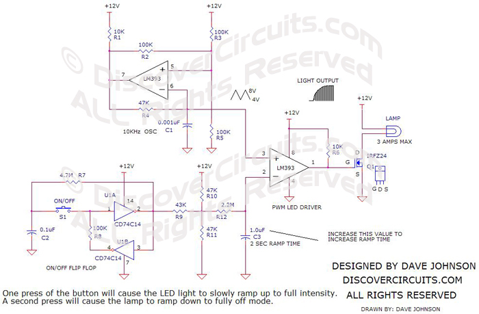
Ramping LED Driver
|
The circuit below was designed to drive a LED with an intensity ramping mode.
Two 555 timers generate two different triangle waveforms. The upper device
generates a 10KHz signal while the lower unit produces a 1Hz signal. The two
signals are fed to a voltage comparator. The result is a pulse width
modulation (PWM) signal, which with the aid of the FET, drives the LED in such a way
that its average light output slowly ramps from about zero light to maximum and then
slowly dims back down. The circuit should operate over a supply voltage ranging
from 3v to 12v. You can easily vary the ramping time by changing the value of the 1M
resistor. For an interesting effect, you can place a 1N4148 diode in parallel
with the 1M resistor, with the cathode (banded end) side connected to pin 3.
|
|
|
|
|
Click on Drawing Below to view PDF version of Schematic |
|
 |
|
|
|
|
|
|