|
13.8V 30-40A Power Supply - Schematic only, a powerfull power supply for my amateur radio equipment using four HEX FET transistors for regulation. Text can be found at: http://www. Agurk.dk/bjarke/Projects/PowerSupplyFET/PowerSupplyFET.htm __ Designed by Bjarke Korsgaard 13cm power Amplifier - Schematic only, no circuit description __ Designed by © 2001 - YO5OFH, Csaba Gajdos
18v AC to DC Power Supply - This is a classic linear power supply which produces a regulated 18v, rated at about 1 amp. . . Circuit by David Johnson P.E.-July, 2006
1A Variable Regulated Power Supply - A 'must-have' for the experimenter. __ Designed by Peter Parker VK3YE
1W HF QRP - Schematic only, no circuit description __ Designed by © 2001 - YO5OFH, Csaba Gajdos
2 Op Amps Provide Averaged Absolute Value - 30-Oct-03 EDN Design Ideas: The circuit in Figure 1 is useful when you need amplitude demodulation or an averaged absolute-value conversion. The circuit comprises two stages, the first of which, IC 1A, is a differential-output absolute-value converter. The second stage, IC 1B, is a traditional differential amplifier. The combination of the two stages performs single-ended absolute-value conversion but only if R3>>R2 Design by Dobromir Dobrev, Jet Electronics, Sofia, Bulgaria
2.5-50V power supply for universal use based on a LT1074 - This project describes a little power supply, based on a LT1074, adjusteable from 2.5 to 50 V, delivering much more than 1 Amp. __ Designed by Alexander C. Frank, aka Ajarn Changpuak
20 Amp (peak) power supply for SSB transceivers - A heavy duty 13.8V power supply is a fine thing to have in the shack, but unless you acquire one secondhand, is an expensive little beastie to buy. This means building one should be considered, not only for the cost savings, but also because you can brag about it on air to your mates. Of course, careful consideration must be given to the properties of the completed supply, and after talking to a few of my friends who have built their own and fallen into all the traps, here are the printable ones : RF proof, easy to make, commonly available parts used, but above all CHEAP. __ Designed by VK5JST / VK5TR
200 Watt Modified PC Power Supply 13.5 Volt 14 Amp - The external 230 Volt AC power ON/OFF switch is removed and bypassed Old unused outputs are removed. Over voltage protection changed to only protect one output at 16 V, Voltage regulating resistor net changed to only monitor a single output __ Designed by OZ2CPU; Thomas from Denmark
200W ATX PC Power Supply - This power supply has ATX design and 200W performance. I was drawed diagram, when I repaired this power supply. This power supply circuit uses chip TL494. Similar circuit is used in the most power supplies with output power about 200W__
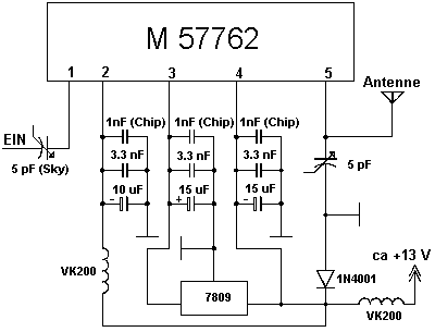
23cm 20W PA with M57762 - Schematic only, no circuit description __ Designed by © 2001 - YO5OFH, Csaba Gajdos
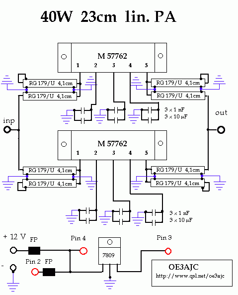
23cm 40W PA with M57762 - Schematic only, no circuit description __ Designed by © 2001 - YO5OFH, Csaba Gajdos
24 Volts AC to 24 Volts DC Power Supply - The idea for the circuit below came from a company needing to power several 24v DC LED assemblies from an existing 24vac supply. They did not need a rock solid and regulated 24 volts but a voltage which hovered around that voltage. Running the AC through . . . Hobby Circuit designed by Dave Johnson P.E.-February, 2011
240VAC to 5VDC Power Supply - This is simple way to power some 5v logic from a 240vac source. if a 120vac power adapter is used, the circuit will also work for 120vac power lines. . . Circuit by Dave Johnson P.E.-February, 2002
24V DC Powered Beeper with 4 Separate Inputs - 24vac is a popular voltage. it is often used in low voltage lighting systems and industrial controls. it is much less dangerous than 120vac/240vac line voltages. This hobby circuit below is one method to efficiently power a cluster of 7 white LEDs from 24vac. . . . Hobby Circuit designed by Dave Johnson P.E.-December, 2009
24-Volt AC Powered Isolated +5V Supply - 24vac is a very popular power supply in many industrial systems. it is often used in systems that involve water. it is also popular with many inside and outside lighting systems. The lower voltage means the danger of human electrocution is much less. . . . Hobby Circuit designed by David Johnson P.E.-July, 2009
25W QRO with PL504 - Schematic only, no circuit description __ Designed by © 2001 - YO5OFH, Csaba Gajdos
26V-to-5000V DC-DC Converter - This circuit can provide 5, 000 VDC from 26 VDC. This circuit has ripple of under 0.01% due to Voltage-doubling capacitors. As sinusoidal oscillator, a 2N217 transistor is used. The diode and the capacitors at the output stage should be of high voltage type. __
2A power supply-An adjustable power supply for Model railways & general projects - This handy power supply has an output of 0v to 12v at 700mA with a transformer that is rated at 1-amp (such as M-2155) or 1.4amp for a transformer that is rated at 2-amp (such as M-2156). Your local electronics shop or model railway supply will have these __ Designed by Collin Mitchell
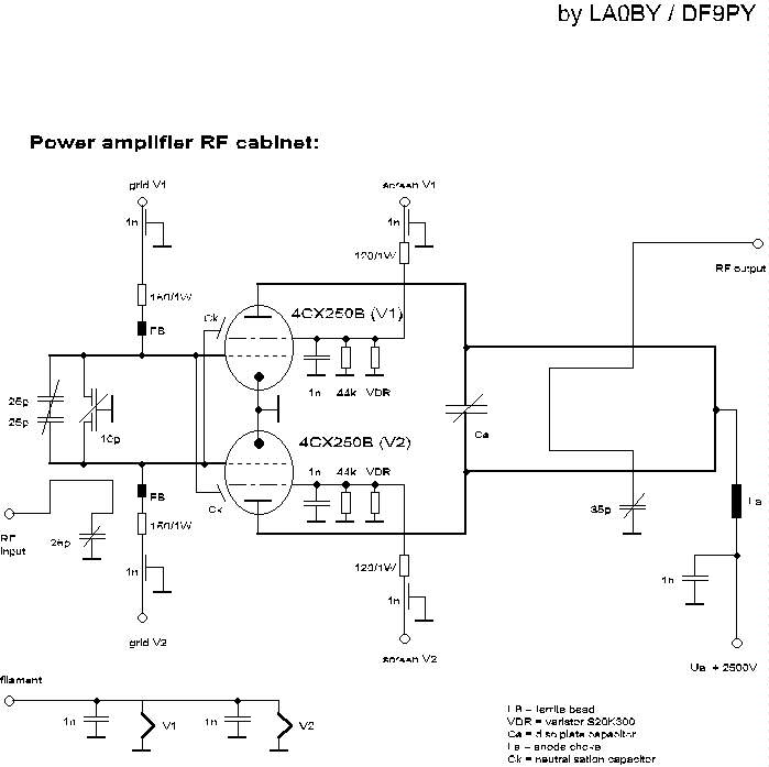
2m power Amplifier - Schematic only, no circuit description __ Designed by LA0 DF9PY
2-Op Amps Provide Averaged Absolute Value - 10/30/03 EDN Design Ideas: The circuit in Figure 1 is useful when you need amplitude demodulation or an averaged absolute-value conversion. The circuit comprises two stages, the first of which, IC 1A, is a differential-output absolute-value converter. The sec Design by Dobromir Dobrev, Jet Electronics, Sofia, Bulgaria
3 Phase Bridge Rectifier - Find out about three phase bridge rectifiers. __ Designed by REUK-Renewable Energy UK website
3.3V Regulated Power Supply - Among the power supplies presented here, this is a well regulated type that can deliver up to 1.5A current from a wide range of input voltage of 5V to 25V dc. See LM317 calculator if you want to know how to get the 3.3 V output. __ Designed by KB Kaminski
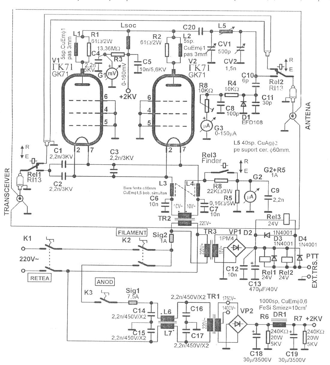
350W QRO with GK71 for 160-15m - Schematic only, no circuit description __ Designed by © 2001 - YO5OFH, Csaba Gajdos
3-Phase Rectifier & Voltage Reducer form a Offline Single-Phase Supplies - EDN-Design ideas -- 04/06/12 Missing diodes create gaps to allow voltage reduction. Design by JB Castro-Miguens, Cesinel, Madrid, Spain; C Castro-Miguens, University of Vigo, Spain; M Pérez Suárez, University of Vigo, Spain; and A Abal Pena, Tekplus, Vigo, Spain
4-20ma Current Loop Tester - This circuit injects an adjustable current through a wire loop. Using a digital current meter, the current can be adjusted from near zero to over 24 milliamps. . . Circuit by Dave Johnson P.E.-May, 2012
432 MHz kilowatt Amplifier - Schematic only, no circuit description __ Designed by W1QWS
5 volt power supply - Schematic only, no circuit description __ Designed by Andy Wilson
500mW HF Linear Amplifier - his project was a particular surprise for me in that the BC547 (equiv 2N2222) can be used to build a 500mW linear amplifer covering the entire HF band with excelent spectral purity and no neutralising at all. Ugly-bug construction was used but I dare say that the good results are partly to do with the method of construction. __ Designed by Harry Lythall-SM0VPO
500W Low cost 12V to 220V inverter - Using this circuit you can convert the 12V dc in to the 220V Ac. in this circuit 4047 is use to generate the square wave of 50hz and amplify the current and then amplify the voltage by using the step transformer. __ Designed by Ashad Mustufa
500W Mos-Fet Power Inverter from 12V to 110V/220V - This circuit will provide a very stable "Square Wave" Output Voltage. Frequency of operation is determined by a pot and is normally set to 60 Hz. Various "off the shelf" transformers can be used. Or Custom wind your own FOR BEST RESULTS. Additional MOSFETs can be paralleled for higher power. it is recommended to Have a "Fuse" in the Power Line and to always have a "Load connected", while power is being applied. The Fuse should be rated at 32 volts and should be aproximately 10 Amps per 100 watts of output. The Power leads must be heavy enough wire to handle this High Current Draw! . __
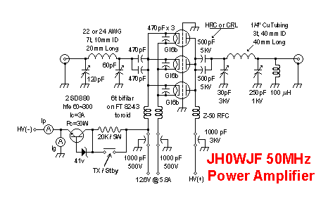
50MHz power Amplifier - Schematic only, no circuit description __ Designed by JH0WJF
50V 3A Stabilized Power Supply with 2N3055 - Many times we needed a stabilized, together regulated power supply and high relatively output voltage. These specifications him it cover our circuit. it 's a circuit that can give in his exit + 40V until + 60V 3A, with simultaneous stabilization. The materials that use is very simple and will not exist difficulties in the manufacture, is enough you are careful certain points.1 ] For output voltages smaller of + 50V until + 40V, the Q1 is hot enough, so that it needs one big heatsink. __
5W QRP with KT907 - Schematic only, no circuit description __ Designed by © 2001 - YO5OFH, Csaba Gajdos
6 to 12 Volt Converter - This circuit can provide up to 800mA of12V power from a 6 Volt supply. The circuit is simple, about 75% efficient and quite useful __ Designed by Aaron Cake
600 Volt Power Supply - Simple 600 Volt DC power supply. Convert 230V AC to 300V and 600V DC. __
60W AC-DC Flyback Converter - Universal AC line input Fully assembled and tested power supply with DC containing all design documentation Features: 0-4A ioutAT15V, 87% efficiency at high line, Short Circuit protection, Over Voltage protection__
78H05 based portable 13,8volt power supply ideal for FT-817 and similar - Ham Radio - Power Supplies __ Designed by Guy Roels ON6MU
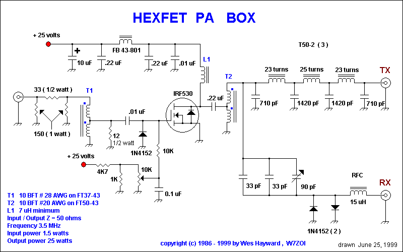
80m hexfet power Amplifier - Schematic only, no circuit description __ Designed by W7ZOI
80V Linear rectifier is Micropower - DN314 Design Notes __ Linear Technology/Analog Devices
90W AC-DC Flyback Converter - Fully assembled and tested power supply with DC containing all design documentation Features: Universal AC line input, 0-6A ioutAT15V, 83% efficiency at high line, Short Circuit protection, Over Voltage protection__
9v Battery Eliminator - if you use 9v battery powered devices for long periods of time, you may get tired of constantly changing batteries. The circuit below can be wired into any 9v battery powered device, drawing power from an external AC to DC power adapter. I designed the circuit. . . Circuit by David A. Johnson P.E.-December, 2009
9-V Stabilized Power Supply - Schematic only __ Designed by Tony van Roon VA3AVR
9-Volt Battery Eliminator - for guitar pedals, radios etc __ Designed by G. Forrest Cook |