|
Fast Charger for Better Lead-Acid Battery Life - This peak limiter is simple and very effective. Uses discrete FET gain control __
Fast Rectifier Circumvents Input-Level Effect - 12/22/94 EDN Design Ideas: All diode-based rectifier circuits suffer from a signal-level-dependent frequency response. This response occurs because the dynamic impedance of the diodes varies as the signal level changes. The result is a slower frequency response and distorted rectified outputs at low signal levels compared with high levels. An alternative approach Design by Michael Steffes and Jim Riphahn, Comlinear Corp, Ft Collins, CO
Fidelity Testing for A to D Converters - Linear Technology AN132 __ Designed by Jim Williams - Oct 1st, 2011
Fixed Voltage Power Supply - The fixed voltage power supply is useful in applications where an adjustable output is not required. This supply is simple, but very flexable as the voltage it outputs is dependant only on the rectifier and transformer you choose. The maximum output current is 1.5A __ Contact IQ Technologies
Form Constant-Current SCR - 02/01/01 EDN Design Ideas: A typical SCR (silicon-controlled rectifier) requires a trigger current, which causes the SCR structure to latch on. Once the device latches, the current through the SCR is solely a function of external component values. The SCR has no inherent ability to limit the current flow once it latches on. Current continues to flow, as long as the current exceeds a minimal value known as the holding current. The circuit in Figure 1 is similar to an SCR, because it also requires a trigger current to latch into its on state. Design by Robert Buono, Ringwood, NJ
Full Wave Rectifier - This is a classic circuit that can accurately convert an AC signal to DC. At 40KHz the input signal can be as low as 0.05 volts peak to peak.. . . Circuit by David Johnson P.E.-July, 2006
Full Wave Rectifier uses Current Feedback Amps - 03/27/97 EDN Design Ideas: Doubling or rectifying a continuous-wave signal by using diode bridges usually causes problems with low inputs or at high frequencies. However, with the use of a 1.2-GHz current-feedback op amp and low-capacitance Schottky diodes in the feedback path, the circuit in Fig 1 can double the input frequency from 100 to 200 MHz Design by Ronald Mancini, Harris Semiconductor, Melbourne, FL
Full-Wave Active Rectifier Requires No Diodes - A full-wave rectifier can be built without using any diodes. it exploits the fact that the output voltage of certain single- supply op amps is effectively clamped to ground (0 V) when the input signal goes negative. __ Designed by Anthony H. Smith
Full-wave rectifier has programmable gain - 11/09/00 EDN Design Ideas: The traditional approach to the design of a full-wave rectifier (Figure 1) is to set the gains of IC 1 and IC 2 to 1 and use the. PDF contains multiple circuits, scroll to find the one of interest Design by Chuck and Chris Wojslaw, Xicor Inc, Milpitas, CA
Full-Wave Rectifier Operates to 200 MHz - 07/20/95 EDN Design Ideas: The circuit in Figure 1 uses current-feedback amplifiers to implement a wideband full-wave rectifier for applications such as a control/AGC system reference or as an amplitude indicator. Putting the full-wave-rectifier diodes in the feedback loop of an op amp works better than does using simple diode-based rectifiers. The op amp's loop gain Design by Rea Schmid, Comlinear Corp, Fort Collins, CO
Generate Boost Rails In a Bridge-Rectifier - 11/16/12 EDN Design Ideas: Bridge ac inputs have the ability to sink and source current with reference to the bridge-rectifier outputs. Many single-voltage power supplies consist of a transformer, a rectifier, and a filter capacitor, as shown in Figure 1. This circuit is relatively inexpensive and easy to build but supplies only a single voltage. Circuits employing op amps, data converters, and other analog circuit blocks often require additional voltages to operate. These extra voltages can be either higher than the main supply voltage or negative. Design by Horst Koelzow, Calgary, Alberta
Good 12 Volt Switching Power Supply - This is a good Circuit for those persons needing to Boost or drop a voltage. The Output is High Frequency, but can be Rectified and Filtered to give DC Out. When Rectifying High Frequencies, You MUST use the Appropriate types of HiGH SPEED Diodes to handle these frequencies. Normal diodes WiLL OVERHEAT and Burn out. __ Designed by G.L. Chemelec
Greatly improve dV/dt immunity of SCRs - 12/09/13 EDN Design Ideas: improve dV/dt immunity of SCRs by three orders of magnitude - The SCR is a switching semiconductor device, whose theoretical basics were published by Moll et al. in 19561. Design by Marian Stofka
Half-Wave Rectifier - This is a conventional inverting amplifier, but with a single supply the output can only provide the positive side of the result. The specific characteristics of the OpAmp provide well controlled clipping behavior__ Linear Technology/Analog Devices App Note,.Jun 21, 2011
HF linear Amplifier with MRF454 - 100W HF Linear Amp - Schematic only, no circuit description __ Designed by © 2001 - YO5OFH, Csaba Gajdos
High Current Power Supply - Since my page was first posted, I have received a number of emails asking about a high current power supply. I looked around, but couldn't find one that was suitable. So, I designed this. it is a linear supply, which might have a few of you rolling your eyes, but it takes very few parts, is simple to build and can supply huge currents. __ Contact IQ Technologies
High current regulated power supply -
Scroll to find this circuit: The high current regulator below uses an additional winding or a separate transformer to supply power for the LM317 regulator so that the pass transistors can operate closer to saturation and improve efficiency. For good efficiency the voltage at the collectors of the two parallel 2N3055 pass transistors should be close to the output voltage. The LM317 requires a couple extra volts on the input side, plus the emitter/base drop of the 3055s, plus whatever is lost across the (0.1ohm) equalizing resistors (1volt at 10 amps) , so a separate transformer and rectifier/filter circuit is used that is a few volts higher than the output voltage __ Designed by Bill Bowden
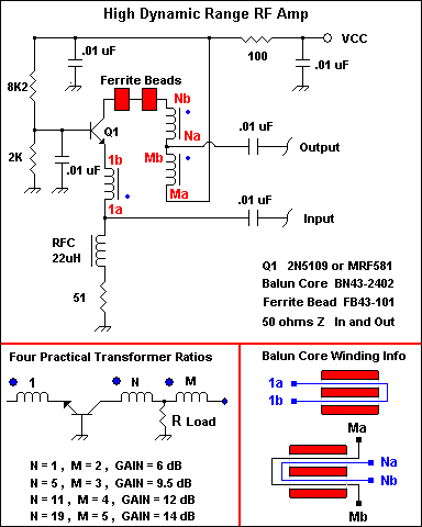
High dynamic range RF Amplifier - Schematic only, no circuit description __ Designed by © 2001 - YO5OFH, Csaba Gajdos
High Efficiency Linear & Switching Solutions for Splitting a Digital Supply - DN172 Design Notes __ Linear Technology/Analog Devices
High Efficiency Linear rectifiers - AN32 Presents circuit techniques permitting high efficiency to be obtained with linear regulation. Particular attention is given to the problem of maintaining high efficiency with widely varying inputs, outputs and loading. Appendix sections review component characteristics and measurement methods. __ Linear Technology/Analog Devices
High IP3, wide band, balanced linear power Amplifier HELA-10 - AN-60-009 Application Note __ MiniCircuits.com
High side PWM Motor/Light Controller - The diagrams are for 12V operation only and there are high side (common ground) and low side (common +12V) versions. The low side version of the circuit uses an N Channel FET, the high side version of the circuit uses a P Channel FET. N Channel devices tend to handle more current than P Channel devices, they are also less expensive. The high side version of the circuit is useful when one side of the load has to be grounded __ Designed by G. Forrest Cook
High-Speed Rectifier Uses No Diode - 03/30/95 EDN Design Ideas: Fig 1 shows a high-speed, full-wave rectifier-or absolute-value circuit-that uses a high-speed clamping amplifier, IC 2. This circuit is faster and performs better than rectifiers employing diodes in their amplifiers' feedback paths. These diode-based circuits have limitations at lower signal-input levels and higher bandwidths. These limitations Design by Paul Hendricks, Analog Devices, Wilmington, MA
Ideal Blocking Diode Circuit for Photovoltaic Solar Panels - Most photovoltaic solar panels are used to charge a battery during the daytime. Nearly all panels come equipped with a blocking diode. The diode prevents DC current from flowing backwards from the battery bank into the panel at night. The usual blocking. . . Circuit by Dave Johnson P.E.-March, 2011
Ideal Diode Function - Most photovoltaic solar panels are used to charge a battery during the daytime. Nearly all panels come equipped with a blocking diode. The diode prevents DC current from flowing backwards from the battery bank into the panel at night. The usual blocking . . . Hobby Circuit designed by David A. Johnson P.E.-January, 2008
Improved Active Rectification - 02/06/03 EDN Design Ideas: Build an adjustable high-frequency notch filter - Rectifiers convert ac signals to dc. You can combine a diode and a load resistor to create a half-wave rectifier, provided that the amplitude of the ac source is much larger than the Design by Reza Moghimi, Analog Devices Inc, San Jose, CA
Instrument panel lamp dimmer control - Motorola - This circuit uses an MC3392 low side protected switch and an MC1455 timing circuit to form an automotive instrumentation panel lamp dimmer control. The brightness of incandescent lamps can be varied by Pulse Width Modulating the input of the MC3392. The modulating signal can be obtained directly from the MC1455 timer (or a microprocessor). The MC1455 is configured as a free-running clock having a frequency and duty cycle control. __ Contact IQ Technologies
Interference Free Switch Mode Pre-Rectifier - I created this circuit to fix an overheating problem with a small Chinese-made stereo set. This simple solution to a perplexing problem worked so well that I felt the need to share it. This circuit can be used for other applications as well. __ Designed by Andrew R. Morris
Inverter 12 volt unit Mos-Fet Design - A Very Reliable, Efficient and Practical Design. Do Not ask how to Build this for Power ratings over 1000 watts, That is NOT Practical. __ Designed by G.L. Chemelec
Isolated Miniature AC/DC Power Supply - This circuit uses a novel approach to produce a fully isolated and regulated 5 volts @30ma from the 120vac power line. it uses two tiny SCRs that alternately discharge two capacitors through a miniature high frequency transformer . . . Hobby Circuit designed by David A. Johnson P.E.-June, 2000 |