|
Op-Amp Current Source with Floating Load including SPICE simulation - The circuit above maintains a current through a floating load RL (neither end is connected to ground.) The key to the circuit's operation is in placing a current sensing resistor RSENSE in the op amp feedback loop. The current delivered to the load RL is: I = Vin / RSENSE How does the circuit work? Three simple functions help this circuit accomplish its goal. (Remember, no current flows into the op amp's input terminals.) __
Op-Amp Rectifier Signals Input State - 07/21/94 EDN Design Ideas: The op-amp rectifier in Fig 1 operates from a single supply and provide as a logic output and an LED that indicate the state of the input voltage. The input-state indications are handy for calibration. Because the circuit operates from a single supply, the 2.5V reference determines the level around which the circuit rectifies input waveforms Design by Lee E Scaggs, High Country TEK, Nevada City, CA
Optimize output-voltage accuracy of adjustable low-dropout regulator - EDN-Design ideas--09/01/98 Optimize output-voltage accuracy of adjustable low-dropout regulators - An adjustable LDO is a good choice when you need a nonstandard voltage, but getting the highest accuracy from one requires a few circuit tricks. --Low-dropout regulators (LDOs) have become common in portable electronic equipment. Their small size, high noise rejection, and low cost make them an attractive solution to a range of system problems—from active power-supply decoupling to local voltage regulation and control. Although LDO suppliers offer several fixed output-voltage settings, some applications require settings that you can't get in an off-the-shelf produ Design by Paul Paglia, Telcom Semiconductor
Output Adjustable Flyback Converter - A high voltage step-up DC power supply using adjustable flyback conversion. __ Designed by Simon Oh
Parasitic Power Supply - This circuit powered a remote doorbell transmitter when a passive IR sensor light was triggered. it had no noticeable effect on the sensor light performance. __ Designed by Andrew R. Morris
Photovoltaic Solar Panels-Ideal Blocking Diode Circuit - Most photovoltaic solar panels are used to charge a battery during the daytime. Nearly all panels come equipped with a blocking diode. The diode prevents DC current from flowing backwards from the battery bank into the panel at night. The usual blocking . . . Hobby Circuit designed by Dave Johnson P.E.-March, 2011
Plus & Minus DC Power Supply - This is a classic example of a regulated DC power supply that produces both a positive 15v and a negative 15v from a 20vac wall adapter . . . Hobby Circuit designed by David A. Johnson P.E.-October, 2005
Poor man's analog to digital converter (ADC) using a 2N222 transistor & a few passives - Years ago some of the then-old engineers working in the cost-completive area of consumer electronics told me, “if it can’t be done with a handful of resistors, caps, a 1N4148 diode and an MPS3904 or MPS2907 transistor, it ain’t worth doing. ” __ Designed by Dave Wissel @ Wave Technology
Portable CD Player Adapter for Car - Whenever i'm in the car listening to my favourite CD, it always happens-my batteries go dead. To solve that problem, I built this extremely simple regulator circuit. it steps down the 12V from the lighter socket to 9V which is used by the CD player __ Designed by Aaron Cake
Power inverter is bidirectional - 08/02/01 EDN Design Ideas: if you want to swap charge in either direction between unevenly loaded positive and negative battery buses, you need an inverting dc transformer. One implementation is the symmetrical flyback converter shown in Figure 1. The circuit Design by Tom Napier, North Wales, PA
Power Jack 3500Watt Inverter - in late 2008 I needed to buy a high power true sine wave inverter, for an alternative energy scheme. Scared away the very poor quality I had seen too many times when asked to repair Chinese inverters, but not willing to pay the outrageous prices asked by manufacturers who are known for their quality products, I settled for a Taiwanese made inverter. it was the Power Jack PSW3500, which is rated at 230V 50Hz output, 12Vdc input (at several hundred amperes, of course!) , __ Designed by Manfred Mornhinweg
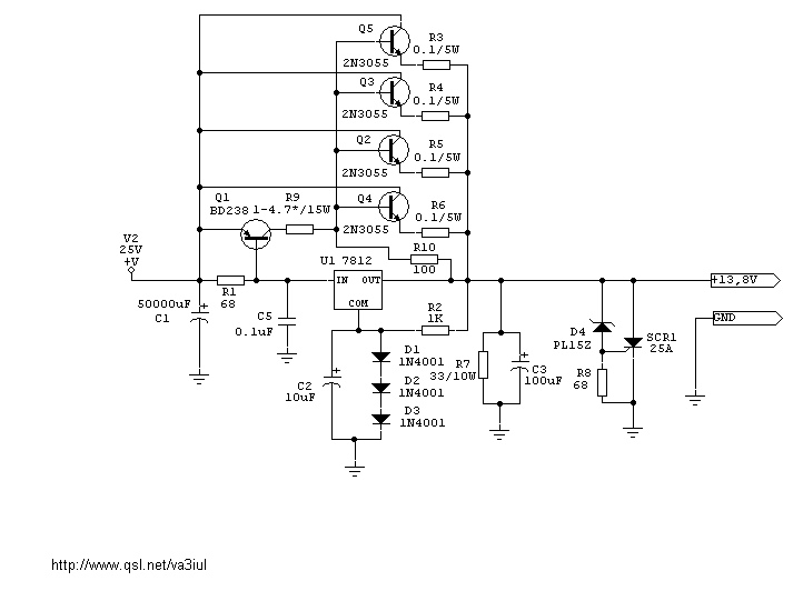
Power Supply 13.8V/20A - Schematic only __ Designed by va3iul
Power Supply Converted from a PC - if you find building your own desktop powersupply from a recycled PSU and a few parts from the local electronics store appealing, then grab some tools, pour yourself a cup of coffee (or personal preference) and let's get started __ Designed by Andy Batts
Power supply for universal use based on an LM317 adjustable regulator - This project describes a little power supply, based on a LM317, adjusteable from 1.25 to 30 V, delivering approx.1 Amp. Yet another nice to have building block :-) __ Designed by Alexander C. Frank, aka Ajarn Changpuak
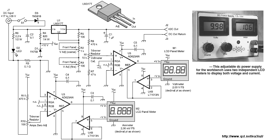
Power Supply LCD meter Display-K1QW - Schematic only __ Designed by va3iul
Power Supply Reversal Correcter-Cum-Preventer - When power-supply polarities of an electronic device are accidentally interchanged, the device runs the risk of damage. The danger can be avoided by adding this tiny circuit to the power supply...__ Electronics Projects for You
Power Supply-24 Volts AC to 24 Volts DC - The idea for the circuit below came from a company needing to power several 24v DC LED assemblies from an existing 24vac supply. They did not need a rock solid and regulated 24 volts but a voltage which hovered around that voltage. Running the AC through. . . Circuit by Dave Johnson P.E.-February, 2011
Precision Fullwave Rectifier - I have used this handy circuit many times. it accurately converts an AC signal into pulsing DC, which can be filtered to provide an average of the input voltage. it works from millivolts to volts. The circuit shown requires a stable +5v reference if a. . . Circuit by David A. Johnson P.E.-February, 2002
Precision full-wave signal rectifier needs no diodes - 09/01/05 EDN Design Ideas: Single-supply design uses two op amps Design by José M Blanes and José A Carrasco, University Miguel Hernández, Elche, Spain
Precision Rectifier Is Glitch-Free to 1 MH - 05/12/94 EDN Design Ideas: The manufacturer’s circuit for a precision, current-mode, full-wave rectifier (Fig 1a]converts a voltage signal to a current, eliminating errors arising from voltage drops across the rectifying diodes. However, just like op-amp-based rectifiers, the circuit Design by Dan Stiurca, "Gh Asachi" Technical University, Iasi, Romania
Precision Rectifier Reduces Ripples - 03/03/97 EDN Design Ideas: You can use a lowpass filter to simultaneously increase a rectifier's speed and reduce or maintain the ripple voltage. The input voltage of the precision rectifier in Figure 1a is 100 mV at a frequency of 50 Hz. The output with C1 equal to0 is a double phase-rectified voltage of R2/R1 Design by W Dijkstra, Waalre, The Netherlands
Precison Power Supply, 0-40V/2A - This Precision Power Supply is a nice addition on your workbench as primary, or in my case, a supplementary power supply. With zero to 40V and 2A with adjustable current limiting it will surely gets lots of use on your bench. On average the most amperage for a power supply someone needs is around two or three amps. The sensitivity for current limiting is fully adjustable. Have fun building! __ Designed by © Doug Bedrosian and Tony van Roon
Protects from Battery Polarity Reversal - This simple circuit can protect a sensitive electronic circuit from an accidental connection of a battery with a reversed polarity. The N-channel FET connects the electronic device to the battery only when the polarity is correct. The circuit shown was . . . Hobby Circuit designed by David A. Johnson P.E.-March, 2002
Pulse Charger for reviving tired Lead Acid batteries - The object is to get the cell voltage high enough for the sulphate to dissolve without boiling or melting the battery. This is achieved by applying higher voltage for shorter periods and let the battery rest for a while. __ Contact IQ Technologies
PV Solar Panels-Ideal Blocking Diode Circuit - Solar panels usually include a diode at their outputs. The diode prevents current from back feeding into the panel at night from the battery being charged by the panel. But, this diode does waste some power and does reduce the available panel voltage . . . Hobby Circuit designed by David Johnson P.E.-March, 2011
PWM DC Motor Speed Control - This is a circuit for controlling the speed of small DC motors, it works nicely as a speed controller for an HO or N gauge model railroad __ Designed by G. Forrest Cook
PWM Motor Speed Controller / DC Light Dimmer - A pulse width modulator (PWM) is a device that may be used as an efficient light dimmer or DC motor speed controller. The circuit described here is for a general purpose device that can control DC devices which draw up to a few amps of __ Designed by G. Forrest Cook
PWM Motor Speed Controller / DC Light Dimmer - A pulse width modulator (PWM) is a device that may be used as an efficient light dimmer or DC motor speed controller. The circuit described here is for a general purpose device that can control DC devices which draw up to a few amps of current. The circuit may be used in either 12 or 24 Volt systems with only a few minor wiring changes. This device has been used to control the brightness of an automotive tail lamp and as a motor speed control for small DC fans of the type used in computer power supplies. __ Designed by Radio LocMan
PWM Motor Speed Controller/DC Light Dimmer - This circuit will work as a DC lamp dimmer, small motor controller, and even as a small heater controller. it would make a great speed control for a solar powered electric train. The circuit has been tried with a 5 Amp electric motor using and iRFZ34N FET and worked ok, D1 may need to be replaced with a faster and higher current diode with some motors. The circuit should work in applications such as a bicycle motor drive system, if you experiment with this, be sure to include an easily accessible emergency power disconnect switch in case the FET shorts out and leaves the circuit full-on. __ Designed by G. Forrest Cook
PWM Motor/Light Controller - The diagrams are for 12V operation only and there are high side (common ground) and low side (common +12V) versions. The low side version of the circuit uses an N Channel FET, the high side version of the circuit uses a P Channel FET. N Channel devices tend to handle more current than P Channel devices, they are also less expensive. The high side version of the circuit is useful when one side of the load has to be grounded __ Designed by G. Forrest Cook
PWM Motor/Light Controller-12V Low & High Side - These two schematics are variations on another PWM circuit that I designed. The diagrams are for 12V operation only and there are high side (common ground) and low side (common +12V) versions. The low side version of the circuit uses an N Channel FET, the high side version of the circuit uses a P Channel FET. N Channel devices handle more current and cost less than P Channel devices. The high side version of the circuit is useful when one side of the load has to be grounded. __ Designed by G. Forrest Cook |