|
2 Transistor FM Voice Transmitter - This simple transmitter operates from a 9V battery as shown above. I personally built this for a purpose. This is how it happened:"members of my singing group find it difficult to handle a FM mic in Church. The choir sings in acapella form and the congregation expect us to perform well. The old FM mic system was not a perfect solution, __ Designed by Andy Collison
2 Transistor LED Flasher - This 1.5 volt LED fasher runs more than a year on a single 'd" cell and alternately flashes 2 LEDs at about a 1 second rate. The circuit employs a 74HC14 CMOS
hex inverter that will operate at very low voltages (less than 1 volt). One section is used as a squarewave oscillator (pins 1 and 2) , while the others are wired to produce a short 10mS pulse on alternate edges of the square wave so the LEDs will alternate back and forth. The output sections each use a capacitor charge pump to increase the voltage for the LEDs __ Designed by Bill Bowden
2 Transistor Transmitter - A compact 2 transistor transmitter for use at VHF frequencies. __ Designed by Rob van der Weijden
2 Valve 40m CW Transmitter - amateur radio construction projects. circuit only, no description given. __ Designed by Peter Parker VK3YE
2 Valve CW Transmitter - This transmitter is very stable and will deliver up to seven watts of power with the components and tubes shown. Do not be put-off by valves as they are VERY easy to work with and it seems that there are quite a few valves around. Because no-one wants these obsolete things they may be bought for next to nothing at radio rally's. if you are not too particular what type of valve you want then there are lots of valves available. __ Designed by Harry Lythall - SM0VPO
2 Watt FM Transmitter - This 2 Watt FM transmitter will provide 10km range in good weather conditions. Use dipole antenna for maximum range. Transmitter can be tuned between 88-108 MHz with c5. BB204 could be replaced with conventional LED (big) with reverse bias (no light given in correct polarity).9v power for 2km transmission with good sound quality and up to 18v for 10km range.2N3553 RF transistors may be replaced with 2N4427 or 2N3866.__
2 Way Morse Practice Set - The first step to learning Morse is to be able to memorise the sounds of all letters and numbers. This can be accomplished with the help of Morse practice tapes or classes. Once you know all the characters, the WiA Morse practice broadcasts and/or continuous VHF Morse beacons can be used to increase your receiving speed. __ Designed by Peter Parker VK3YE-first appeared in Amateur Radio, April 1998
20-meterband (14Mc) 0.5 watt AM/CW transmitter - in this project, you will make a simple low-power broadcast-type circuit, using a crystal oscillator integrated circuit and an a collector modulated AM oscillator. You can connect the circuit to the an electrec microphone (pointed out in gray on the diagram) or amplified dynamic microphone (no amplified microphone has a to low output voltage to work. Approx.100mv is needed). You could also add a LF preamp stage of one transistor to allow connecting a dynamic microphone directly. __ Designed by Guy Roels ON6MU
20W FM Amplifier - This Power amplifier is equiped with two Philips bipolar transistors : the BLV10 & BLW87. As lots of FM amplifier design, the RF transistors are in a class C bias. The FM amplifier has a 21 dB gain with a 55 to 65% efficiency. __
222 MHz Transverter - The original project was published in July'93 QEX magazine. Before starting construction, collect all the parts to complete the 3 boards in the design: circuit boards, semiconductors, and surface mount parts, wire for inductors, xtal, toroid form, etc. in addition you may want to consider a case, connectors, PA, or front end switching (you may not require it, depending on the radio you use for an iF - or can be done with almost any small 12v relay). You may also need to build a 3 resistor pad to reduce the Tx RF level from your transmitter __ Designed by Original Zack Lau W1VT, this project and supplemental notes Rick Bandla VE3CVG
23cm 20W PA with M57762 - Schematic only, no circuit description __ Designed by © 2001 - YO5OFH, Csaba Gajdos
23cm 40W PA with M57762 - Schematic only, no circuit description __ Designed by © 2001 - YO5OFH, Csaba Gajdos
23cm ATV FM Transmitter - Schematic only __ Designed by va3iul
2-5 Km Long Range FM Transmitter - The proposed long range transmitter circuit really is very steady, harmonic free design which you can use with standard fm frequencies between 88 and 108 MHz. This will likely encompass 5km spectrum (long range). it includes an extremely consistent oscillator for the reason that you employ LM7809 stabilizer that is a 9V stabilized power source for T1 transistor and for frequency realignment that may be reached by means of the 10K linear potentiometer. The output strength of this long range rf transmitter is approximately 1W. Transistor T1 is employed as an oscillator stage to present a small power steady frequency. To fine-tune the freq. apply the 10k linear potentiometer this way: should you moderate, in the direction of ground, the freq. would probably decrease but when you fine-tune it in direction of + it would climb. Essentially the potentiometer is needed just as a flexible power source for the a pair of MV2019 varicap diodes. Both of these diodes function as a changeable capacitor whilst you regulate the pot. By tweaking the diode capacitance the L1 + diodes circuit renders a resonance circuit for T1. Feel free to employ transistors similar to BF199, BF214 however be careful not to use BCs. At this point you don’t receive yet the long range fm wireless transmitter due to the fact that the electric power is fairly reduced, a maximum of 0.5 mW.__
250mW FM Transmitter Amplifier - This project is a simple 2-transistor VHF power amplifier, with about 16dB gain, and requires no tuning or alignment procedures. Wideband techniques have been used in the design and the circuit is equipped with a "lowpass" filter to ensure good output spectral purity. The project has been designed for assembly on a single-sided printed circuit board. The circuit is specifically designed to amplify the output of 7mW to 10mW WBFM transmitters (wide band) to a final level of 250mW to 300mW.__
250mW FM VHF Transmitter - This FM VHF transmitter will output approximately 250mW of RF power using a 2N3866 output transistor and can operate between 75MHz and 146MHz. it utilities a variable high gain audio pre-amplifier which can detect voices 40 feet away using an electret microphone. Using a NBFM scanner, ranges over 5KM have been achieved using a 48cm wire antenna. Coils are 22SWG 7mm air core. L1 and L2 should be 6 turns for 75MHz to 85MHz, 4 turns for 85MHz to 100MHz and 3 turns for 100 to 146MHz. For frequencies over 100MHz the Crystal will be higher than 20MHz hence the base emitter capacitor should be 47pF. L3 is a 4.7uH choke. it is ideal to tune up this circuit using a wave detector meter placed a few inches away from the transmitter.__
250mW HF CW Transmitter - Here is a simple little HF TX. it may be modified for all the HF bands, but the details given are only for the 7MHz band. __ Designed by Harry Lythall-SM0VPO
25W QRO with PL504 - Schematic only, no circuit description __ Designed by © 2001 - YO5OFH, Csaba Gajdos
25W RF Amplifier - RF amplifier with 25W of power for 88-108MHz FM transmitters __ Designed by suthus55 @ hotmail.com
27MHz AM /CW Transmitter - This site timed-out when I tried to load it. __ Designed by Harry Lythall-SM0VPO
27Mhz FM 0.5W transmitter - My Radio amateur callsign is OZ2CPU. I like to use Atmel AVR Atmega PIC 16 PIC 16F876 PIC 16F84. Most electronics easy made for the novice and something is for the more experienced. __ Designed by Thomas Scherrer OZ2CPU
27MHz toy car receiver - RF circuits are not easy to build. The purpose of this page is to make the circuit diagrams available for educational purposes. I won't be able to help you contructing them or give more info than what is written on this page. __ Designed by Peter Jakab
27MHz Transmitters - in this discussion we cover 27MHz transmitters and receivers as found in remote control cars, aeroplanes, walkie talkies and some of the older-style garage door openers. We have provided a number of circuits so you can work out the best type for your application and these circuits will also help you understand which components are critical __ Contact Collin Mitchell
27MHz/ 49 MHz Walkie Talkie - Lots of people are requesting walkie-talkie and RF remote control schematics, so here is some. Building these circuits needs special equipment and expertise in RF circuits. if you are going to experiment with these circuits, please __ Designed by Peter Jakab
28W FM Broadcast Transmitter Amplifier 88-108 MHz - This RF Amplifier designed for FM broadcast using a single 2SC1946 VHF Power Transistor. This 10-30W RF amplifier circuit provides an appropriate power boost with an input of 1-3 watt. Tower are 30 meters high will send signal surrounding air should be around 15 km. The layout of the 2SC1946 28 Watts FM broadcast RF amplifier has been created with Eagle. The pcb outline is 100 x 50 mm (width x height) , all bitmaps have a resolution of 600dpi.Use FR-4 single sided photoresist epoxy pcb material for best results.__
2km Long Range FM Transmitter - The power output of many transmitter circuits are very low because no power amplifier stages are incorporated. The transmitter circuit described here has an extra RF power amplifier stage using 2N3866 RF power transistor after the oscillator stage to increase output power to 250 milliwatts. With a good matching 50-ohm ground plane antenna or multi-element YagI antenna, this transmitter can provide reasonably good signal strength up to a distance of about 2 kilometers. Transmitter's oscillator is built around BF494 transistor T1. it is a basic low-power variable-frequency VHF oscillator. A varicap diode circuit is included to tune the frequency of the transmitter and to provide frequency modulation by audio signals. The output of the oscillator is about 50 milliwatts.2N3866 transistor T2 forms a VHF-class A power amplifier. it boosts the oscillator signal power four to five times. Thus 250mW of power is generated at the collector of transistor T2.__
2km TV Transmitter - Here is a simple TV transmitter. The circuit is simple and really quite crude, but it does include MONO sound. I have not shown the two regulators in the drawing. These are one 12v DC 1A series regulator chip, and one 8v DC 1A series regulator. I fed the 8v regulator from the output of the 12v regulator. The rest of the circuit looks like this. it is a free-running Variable Frequency Oscillator (VFO) using just one coil and one capacitor to determine the frequency. Change this as you will. The basic circuit uses a 150pf from the Base of the RF transistor to ground, so that TR2 operates as a "common-base mode" (grounded base) amplifier. The tuned circuit in the collector and the capacitor from collector to emitter provide tuning and feedback.__
2m (144MHz) Dual Gate FET Low Noise Amplifier - My good old FT-290 2m SSB and FM radio, had about 1uV sensitivity before installing this amp.
Now it is 150nV just like the best radios I have tested. Stations I could hear with noise, are now loud and clear ! ! __ Designed by Thomas Scherrer OZ2CPU
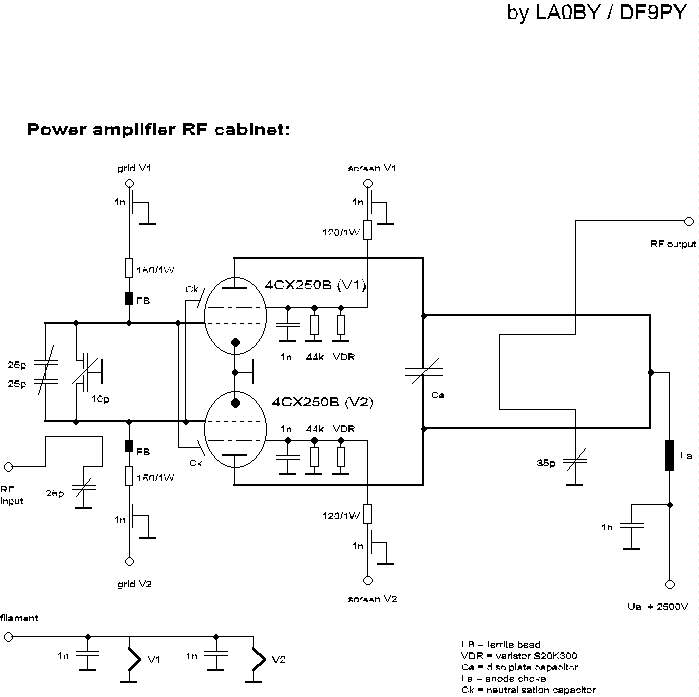
2m power Amplifier - Schematic only, no circuit description __ Designed by LA0 DF9PY
2m-20m Transverter - This little circuit is a transmitting and receiving converter (transverter) that converts a FT290 or similar multimode handheld transciever to the 14MHz amateur band. The project is a single board module that needs an external local oscillator, for example, the VHF harmonic oscillator (or QRP VHF FM TX) LO for transverter project. it should be a relatively simple matter of scaling coils __ Designed by Harry Lythall-SM0VPO
2N2222 40 Meter CW/DSB Tranceiver - in spring of 1998, NorCal sponsored a contest to design and build a project using no ICs and 22 or fewer 2N2222s as the active semiconductor devices. I thought this was a really intriguing idea, so I set about to design my version __ Designed by Monty Northrup
2-Transistor FM Transmitter - While there are a plethora of similar 2-transistor schematics available, this one is above average. A major improvement over the little 1-transistor circuit that we've discussed previously this transmitter__ tomzi.geo page
2W RF Amplifier for 24/23 CM - This page describes TX ATV Transmitter for 23 cm with output adjustable from 100 to 250mW__
2-way Morse practice set - The first step to learning Morse is to be able to memorise the sounds of all letters and numbers. This can be accomplished with the help of Morse practice tapes or classes. Once you know all the characters, the WiA Morse practice broadcasts and/or continuous VHF Morse beacons can be used to increase your receiving speed. __ Designed by Peter Parker |