|
10 MHz, Lumped Element, Anti-Aliasing Filter Design for High Speed 40 MHz A/D system - This classical, 5 stage, 50 ohm, Anti-Aliasing filter was designed for a high performance 40 MHz, 12 bit sampling A/D converter. During the design phase, careful models were made of the inductor and capacitor Q's so that the design could be optimized without having to resort to many trial and error breadboards. One breadboard was made to characterize the components and a second breadboard was done to finalize the design. Monte Carlo analysis was preformed to verify the design over temperature __ Designed by Steve Hageman
100 Watt RF Power Amplifier for 2 GHz - Turn an old 1.9 GHz PCS cellular phone basestation into a RF power amplifier. __ Green Bay Professional Packet Radio
100kHz to1GHz RF Power Detector - LTC5507) __ Linear Technology/Analog Devices
100W FM Amplifier - This Power amplifier is equipped with a bipolar transistor, the famous MRF317 As lots of FM amplifier application , the power transistor is in a C class bias. All the impedance networks (Input & Output) have been determined by using the __ Designed by Michel P
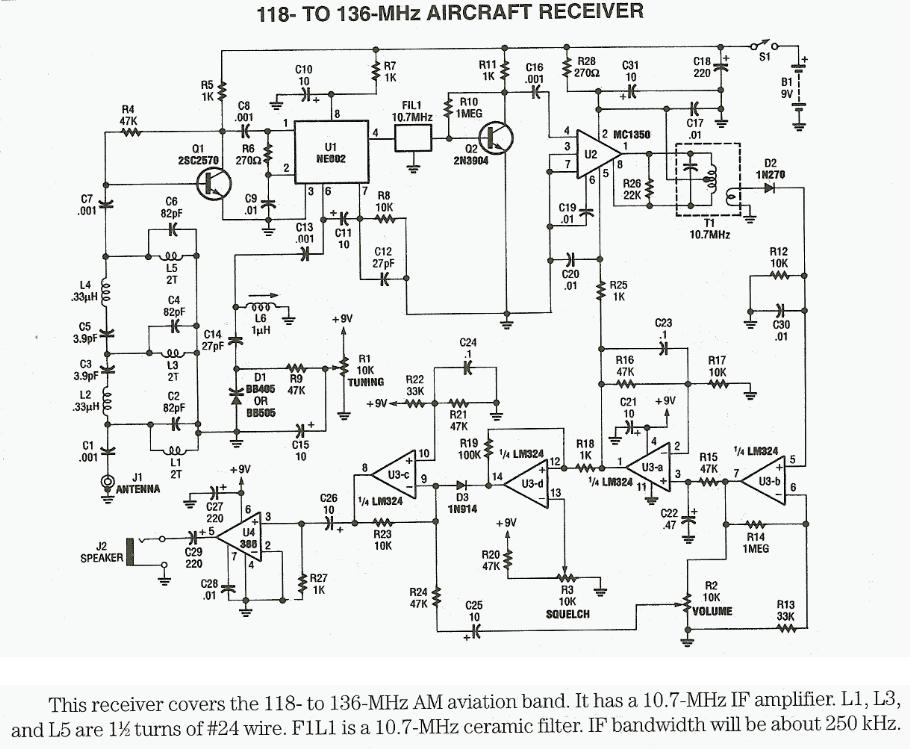
118MHz to 136MHz aircraft receiver - Schematic only, no circuit description
12 to 1 RF, 25 GHz switch matrix (Solid State) - This 12:1, solid-state RF switch matrix was built for a test system application (Test and measurement application). The four layer PCB was designed with Coplanar waveguide over groundplane and Stripline techniques for very low sensitivity to manufacturing tolerances and very low assembly costs __ Designed by Steve Hageman
13.8V 30-40A Power Supply - Schematic only, a powerfull power supply for my amateur radio equipment using four HEX FET transistors for regulation. Text can be found at: http://www.agurk.dk/bjarke/Projects/PowerSupplyFET/PowerSupplyFET.htm __ Designed by Bjarke Korsgaard
1300MHz-1500MHz antenna with Amplifier based on two MAR-8 RF Amplifiers - Schematic only, no circuit description
144 MHz 125W Power Amplifier - Schematic only __ Designed by va3iul
144.00 Mhz 1.5Watt CW transmitter - The Xtal osc is riped from an old AT-PC running 16MHz, it requeres 5.0 volt and use 18mA
those Xtal oscilators is accurate and needs no adjustment
The 5.0Volt 7805 regulator can also be ripped from the same old PC, then this transmitter, can be created for nomoney at all! The CW-Keying is done by turning the PA-stage on or off with a P-channel FET or a PNP transistor
The PA transistor (2N4427) gets a bit hot, this can be solved by incerting a resistor in the collector/powersupply, to reduse output to about 800mWatt. __ Designed by Thomas Scherrer OZ2CPU
160m mini portable End Fed Half Wave Tuner-MkII - A small portable 160m EFHW tuner design. This is the mini version of the previous version. The air core inductor is replaced with a toroid and the variable capacitor is replaced with a fixed capacitor combination. __ Designed by S.Spirat, Steph de VK5ZVS
18 DB LT1253 DDS Amplifier - This 18 dB gain amplifier was built Manhattan-style to evaluate the LT1253 dual video amplifier as a candidate output amplifier for DDS systems employing the Analog Devices AD9850 and similar devices. This dual amplifier was chosen to take advantage of its high gain-bandwidth product. By utilizing both amplifier sections, a very broadband (100 KHz to 30+ MHz), high gain system could be built. __ Designed by Jim Kortge, K8IQY
1-Transistor Amplifier/Detector - An amplifier may be added to boost the audio level as shown below. The current consumption of this amplifier is quite low and a power switch is not included. Disconnect the battery when the receiver is stored for long periods. __ Contact: Charles Wenzel of Wenzel Associates, Inc.
1W RF Power Amplifier for iPOD Stereo FM transmitters - This project explain how you can build and connect a powerful 1W amplifier to your FM transmitters. A perfect solution for those wishing to listen to their favorite tunes in the car, house, garden, school, campus, party, you name it. Why not share your music with every one else in your city!
2 Channel RF AVR Remote Control - How many times you needed some remote control to handle some electric device ? many times. There are lot of remote controls like infrared, RF, SMS (like my other circuit) and more. The basic small-range remote controls are 2, Infrared and RF (Radio Frequency). One of the weaks of Infrared is that the signal can not pass the walls. So, if you want to control your garage door, the only way is to use some RF remote control. The circuit (transmitter and receiver) use few components and ordinary (I love few component circuits). Its easy to build it because you don't have to tune-up any coil or variable capacitor. The RF modules are fix to work in 418MHz area. __ Designed by Vassilis Serasidis
2 Transistor Reflex Radio - Schematic & PC Board, no circuit description] __ Designed by © David Hoult
2.3 GHz Power Amplifiers - Note: quality of text is poor. __ Designed by RL Campbell KK7B
2.3GHz to 432MHz RX converter for Yaesu FT817 - This very small RX converter fits on the backside (yes the small side at the back) of the Yaesu multiband allmode transceiver FT817. And it even operates on the internal batteries of the transceiver (without modification of the FT817). And it can be configured for either input frequencies around 2320 MHz or for the satellite downlink at 2.4GHz (very interesting for receiving satellite signals from the new phase 3D amateur radio satellite). Design is completed for quite some time, I just have to do the documentation. I will try to publish it asap. __ Designed by Herbert Dingfelder
2.45ghz RF Signal Detector - This passive RF indicator is made from a few simple parts. A 100uA moving coil meter is used to display the relative intensity of the RF signal. This circuit can be used with some cell phones and many cordless telephones. . . Circuit by David Johnson P.E.-July, 2006
20dB VHF Amplifier - The amplifier is a circuit of high frequency RF with distinguishable materials. The amplifier as circuit strengthens the tendency of signal with concrete aid, depending on the frequency of signal. If the frequency of signal is included in the limits of spectrum of frequencies. __ Contact: IQ Technologies
23 DB Bipolar DDS Amplifier - Some recent discussions with George Heron, N2APB and Craig Johnson, AA0ZZ regarding alternatives to using MMICs as amplifiers in DDS applications lead to the design of this 23 dB shunt feedback amplifier. This version is setup to operate at 12-13.8 volts, but with minor changes, can be made to operate with supply voltages as low as 5 volts. __ Designed by Jim Kortge, K8IQY
2304 & 3456 MHz Power Amplifiers - Note: quality of text is poor. __ Designed by Greg McIntire AA5C
25W FM MOSFET RF power Amplifier based on BLF245 - This new FM Power amplifier is equiped with the famous MOSFET transistor: the BLF245.
Depending on the output power level your FM synthesizer is able to provide, you can use or not the 2N4427 driver stage. We've chosen the synthesizer n°1 (described on this Website) to drive this amplifier unit. By the way,we will use the 2N4427 driver stage to boost properly the BLF245 __ Designed by Michael P.
2m (144MHz) Dual Gate FET Low Noise Amplifier - My good old FT-290 2m SSB and FM radio, had about 1uV sensitivity before installing this amp.
Now it is 150nV just like the best radios I have tested. Stations I could hear with noise, are now loud and clear !! __ Designed by Thomas Scherrer OZ2CPU
2-transistor Radio - Here is a simple radio that was designed to minimize unusual parts; there isn't even a detector diode! The sensitivity isn't as high as the one-transistor reflex but the simplicity is attractive. Strong stations will provide plenty of volume __ Contact: Charles Wenzel of Wenzel Associates, Inc.
2W RF Amplifier for 24/23 CM - This page describes TX ATV Transmitter for 23 cm with output adjustable from 100 to 250mW
|