|
 |
Circuits designed by David Johnson, P.E.
Last Updated on:
Monday, December 25, 2017 02:08 PM
List of Dave's Circuit Designs
The contents & graphics of
Discovercircuits.com are copyright protected.
LINKING to Dave's circuits is permitted but DO NOT COPY any files to ANY WEB SITE
server |
|
|
|
|
More
Latching Circuits |
|
ON/OFF LATCH CIRCUIT WITH 2 SECOND DELAY
June 30,
2013 |
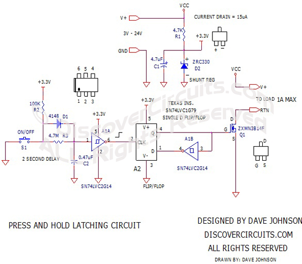
| A Discover Circuits visitor
needed a latch circuit which could operate using a power supply voltage ranging from
3v to 24v. He wanted to use a tiny pushbutton switch to turn on and off power to
a load. However, he wanted a 2 second delay between the switch activation and
the state change of the output. The delay would prevent accidental activation of
the circuit from a quick push button switch closure. The circuit below performs this
function. A dual Schmitt trigger inverter IC and a single flip/flop IC form the
heart of the circuit. The A1A section performs the 2 second delay function. |
|
|
|
The Q
output of the flip/flop is inverted by the A1B inverter section and fed to the flip/flop’s
data input. This configuration forms a data type flip/flop which changes state with
each leading edge pulse from the A1A inverter. The transistor chosen should be able
to handle about an Amp of current. I used a 3.3v shunt type voltage regulator, which
draws about 15ua of current from the supply voltage to limit the voltage fed to the
circuit to 3.3v but the circuit can operate fine from a 3v supply. In fact, the
latch circuit will operate below 1v but at such a low voltage the Q1 transistor will not
fully turn on. If the supply voltage is limited to 5v, the shunt regulator is not
needed and the circuit will operate while drawing a very low current of about 1ua.
|
|
|
Click
on Drawing Below to view PDF version of Schematic |
|
 |
|
|
|
|