|
DiscoverCircuits.com -- Hobby Corner
Last Updated on:
Tuesday, June 01, 2021 03:06 PM
Hobby Circuits List
The contents &
graphics of Discovercircuits.com are copyright protected.
LINK to Dave's circuit, but DO NOT COPY any files to your WEB
SITE server |
 |
|
|
|
|
|
|
More
Battery Chargers
Opto-Isolators |
|
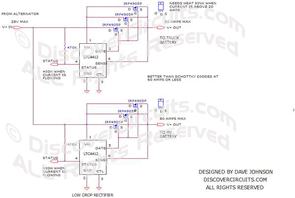
Two 12v Battery Isolator Circuit
with a LTC4412
designed
by David A. Johnson, P.E. |
| Linear Technology has
just announced a neat little chip (LTC4412). It has been designed
to be used in
conjunction with an external P-channel power FET, to form an ideal diode function
with a very low 0.05v voltage drop. The chip monitors the voltage on either side of
the FET. |
|
| As
long as the voltage on the drain side is greater than the source side, the FET is turned
on. The device controls the voltage at the gate of the FET to maintain a voltage drop of
about 0.05 volts across the FET. When the current direction tries to reverse, the hobby
circuit senses the voltage polarity change and turns off the transistor, blocking the
current. This action mimics how an ideal diode would function. The circuit below shows
how this device can be used with a FET from International Rectifier, to form an ideal
diode with a rating of 20 Amps and a voltage up to 28v. |
|
How are these devices used? Let�s suppose
you owned a recreational vehicle (RV). When the RVs engine is running, you
would like the engine�s alternator to charge both the engine�s battery and the
battery used in the RV. But, when the engine is off you don�t want the 12v RV
loads to pull current from the engine battery. Likewise, you don�t want to
pull current from the RV battery when the engine is running. One way to solve
this problem is with the use of two diodes. The alternator output of the
engine is fed to the anode side of two power diodes. One diode routes current
to the engine�s battery while the second diode routes current to the RV battery. |
|
|
|
The diodes
block any current path between the two batteries. In a conventional circuit, two
high current diodes would be used. But, since there could be a sizeable current
passing through the diodes, they have to be mounted onto a large heat sink, to be able
to handle the power dissipated in the diodes. The circuit shown below is much more
efficient. It shows this battery isolator using two ideal diodes. With the
components shown, the electronic circuit should be able to handle 60 Amps of current to
each battery. |
|
|
Click on Circuit Below to view PDF of Schematic |
|
 |
|
|
|
More
Battery Chargers
Opto-Isolators
Hobby Circuits List
eMail David A.
Johnson, P.E. about this circuit |