|
DiscoverCircuits.com -- Hobby Corner
Last Updated on:
Wednesday, June 02, 2021 06:28 AM
Hobby Circuits'
Category List
The contents &
graphics of Discovercircuits.com are copyright protected.
LINK to Dave's circuit, but DO NOT COPY any files to your WEB
SITE server |
 |
|
|
|
|
|
|
More
Alarm Circuits
Freezer / Frost Alarms |
|
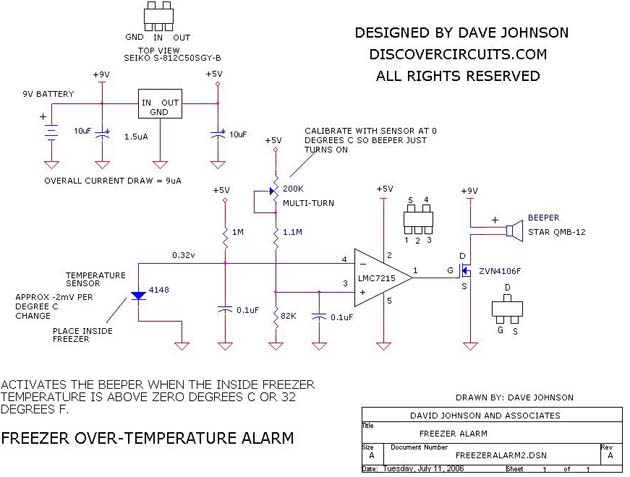
Freezing Temperature Alarm
designed
by David Johnson, P.E. |
|
This electronic hobby circuit below is designed
to activate a beeper alarm, whenever the outside air temperature is below 0 degrees
C (32F). A 9v battery powers the hobby circuit. The average 9ua current
is so low that the battery should last for many years. |
|
|
An accurate glass bead thermistor is used as the
temperature sensor. Other sensors may have been possible, but by using a
thermistor, the overall power consumption can be kept low. A small gage unshielded
cable can be used to link the temperature sensor to the hobby circuit. The cable length
can be up to 20 feet for a small gage wire and longer if you use a heavy gage wire.
The electronic circuit can be housed in a small plastic box. Some boxes have nice
snap out compartments for a 9v battery. |
|
A very low power +5v regulator is used to
provide a solid +5v for most of the circuit. A single low power voltage
comparator (LM7215) from National Semiconductor is used to compare the voltages
across a bridge network, consisting of the thermistor and a 499K resistor on one
side and a 720K and a 1M resistor on the other side. When the temperature is
below freezing, the voltage at the non-inverting input exceeds the inverting input,
causing the output of the comparator to swing from zero volts to +5v. The 5v
signal at the gate of the FET then turns on the transistor, which turns on the
beeper.
|
|
|
|
|
Click on Circuit Below to view PDF of Schematic |
|
 |
|
|
More
Alarm Circuits
Freezer / Frost Alarms
Hobby Circuits'
Category List
eMail David A.
Johnson, P.E. about this circuit |