|
Railpower Model Train Controller, Pt.2 - Last month we presented the circuit, specifications and parts list for our new high-performance Railpower IV model train controller. Now it's time for the construction details - and we show you how to set it up for best performance.__ SiliconChip Railway Model Train Controller Pt 3 - As promised in part 2, here is the walk-around throttle version of the Railpower speed control for model railways. It uses four switches to control speed, forward/reverse, inertia and braking.__ SiliconChip
Railway Points Sequencer - Dedicated model rail enthusiasts using sophisticated train and points controllers often have the problem that as their layouts get bigger and more complex, the transformer supplying power to the points does not have enough current to switch several points at the same time. The actuators in the points are designed for ac operation so it doesn’t help by rectifying the supply and adding reservoir capacitors, the coils can overheat and burn out__ Learning Electronics
RCFS - Our original R/C Fail-Safe project. It has been replaced by RCFS-V2 (see above) . __ Designed by T. Black
RCFS-V2 - Add R/C Fail-Safe features to any servo. A microcontroller continuously monitors the servo's pulse signal and it takes over if the transmitted R/C signal is bad. For use with PPM (AM/FM) Rx's. __ Designed by T. Black
RC-Mon - Build your own low cost R/C frequency monitor. You can use this to check for interference from other transmitters and glitch inducing noise sources at your flying site. __ Designed by T. Black
RCST - R/C Servo Tester. This pocket sized device is perfect for checking and testing your servos. It features digital accuracy and convenient features, including a servo exercise mode. __ Designed by T. Black
Receiver Battery Low Voltage Alarm - Here is another equally cool low voltage alarm circuit for your glider receiver battery that I've shamelessly stolen from George Steiner's book "A to Z--Radio Control Electronic Journal" (see below) . I've modified it to use with small battery packs in R/C gliders. This design has a trigger voltage at about 4.3 volts, and it draws 1mA or less when quiet and about 4mA when buzzing. This can be constructed from parts fromt Radio Shack, though you may need to order a few through them. __ Contact: Rob Crockett
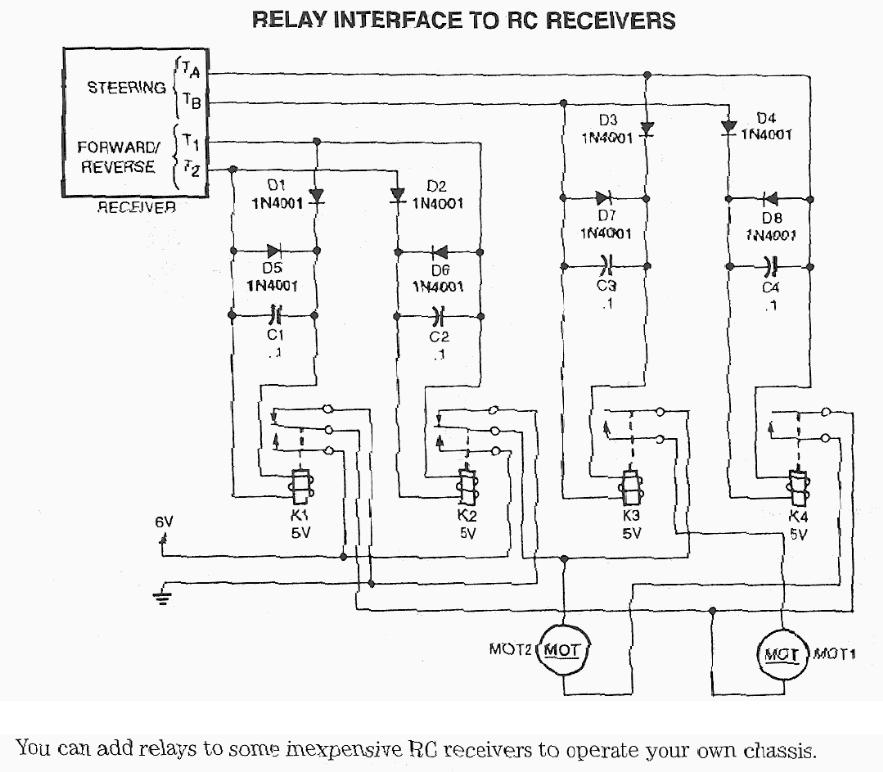
Relay interface to R/C receivers - Schematic only __ Designed by Petr Prause, OK1DPX
Remote Control for Toy Car - Make any battery-operated toy car remote-controlled using this circuit. The circuit, consisting of an infrared transmitter-receiver pair, uses IR beam transmission to switch the toy car 'on' or 'off '. To...__ Electronics Projects for You
Revisited-Model Train Lighthouse Flasher - This was originally designed for a model in a HO train set. It simulates the behavior of the light from a lighthouse. The LED intensity gradually increases, then flashes with a bright light and finally decreases slowly in intensity . . . Hobby Circuit designed by David A. Johnson P.E.-July, 2006
RF Modem RobotICs Project - RF is just way too cool not to use in your designs. But if you're a newbie like me it is difficult to successfully build solid RF transmitters and receivers. When I started out I didn't realize that the larger breadboard I was working off of was causing a lot of the signal deviance because the metal traces on the breadboard worked like small capacitors and changed my circuit Dynamics. So after much research I found the Reynolds Electronics RWS and TWS 434 RX/TX pair __ Designed by Rob Arnold
Rocket Ignition SystE - M - The problem with most model rocket launch controllers is that the battery is located with the operator, far away from the launch pad. This requires thick cables and wastes significant energy. By locating the battery near the rocket engine and using a remotely-controlled relay, the improved launch system is more efficient but can still be built at home. Includes complete schematics, the pcb layout, and source/object code. __ Contact: David Cook
Serial PWM PIC with Direction Pins Latched - Several Projects, scroll down. I have decided to move up from using hacked servos as my drive motors, I wanted more powerful drive motors! To do this you really need PWM. Pulse Width Modulation is the process by which you vary the duty cycle of the drive signal to a motor, without changing the frequency. Basically, if you have your PWM set to 10% of the total possible "on" time then the motor runs at 10% speed, at 75% it runs at 75% of max speed, and so on. In fact however it usually takes more of a "punch" to get a motor to start than it takes to keep it going____ Designed by Dennis Clark
Serial Servo Controller on a PIC 12C508 - Several Projects, scroll down. This is a lot harder than you would initially think. Its a bit of real-time programming on a controller that is only running a 4MHz clock. Not great for servos in my opinion. I send a single byte where the upper two bits defines the servo, 0-3 and the lower 6 bits defines the position. On the PIC I then multiply the 6 bit number by 4 giving numbers from 0 to 252 in increments of 4____ Designed by Dennis Clark
Servo Wiring Chart - After 1991 or so (I can't remember) , most of the major brands of servos became compatible with each other. You can use any of these brands of servos with any brand of receiver. Some brands of servos are really great for a particular use in a particular plane, and there are other companies that sell their servos with each different
Shunting Lights for DCC Locomotives - Digital decoders in model locomotives usually have two outputs for lighting functions. One switches the front lights for forward travel, and the other for reverse travel. If the locomotive has red rear lights, they are also connected to the two outputs. Many digital decoders include function mapping capability, which allows the switch functions to be assigned as desired. For example, with function mapping you can control the lighting not only for normal running, but also for shunting yard operations with the lights lit at both ends of the locomotivemust register on this site __ Designed by Published in Elecktor July/Aug, 2010
Signal Breaking Module - Brake modules are electronic circuits that let locos with digital decoder brake smoothly on a section of track. The brake module generates a brake voltage to be fed to the track that is interpreted by suitable loco decoders, which then smoothly brake the loco. The brake voltage is basically just negative dc, but on the bogobit brake modules (except for the standard brake module) combined with a tailored current limit protection to avoid critical short circuits. __ Designed by Manfred Boehmel
Signals (train signals) - Signals that ACTUALLY operate add a high degree of realism to any model railway as well as being something additional for viewers to watch. Unfortunately they are sometimes omitted due to the complexity of controlling them realistically. This article describes a module than can be readily fitted into an existing layout and used to control either two-aspect or three-aspect signalling systems __ Contact: Collin Mitchell
Simple Circuit Flashing Light 1 - This project uses a 3909 IC and a few other parts; power is 1.5 volts DC. __ Designed by ML Rollins
Simple Circuit Flashing Light 2 - This project uses parts from Digi-Key __ Designed by ML Rollins
Simple Circuit Flashing Light 3B - The simplest flashing light circuit in the world! This is the simplest flashing circuit, suitable for tops of tall buildings, smokestacks and water towers __ Designed by ML Rollins
Simple Circuit RC car for beginners (Android control via Bluetooth) - This is a simple project of Android Bluetooth Car with Bluetooth control. Arduino controller is used. To control the car used Android-device with a built-in accelerometer. Tilt forward - car goes forward, tilt to the left - car turns to the left, tilt back - car goes back.
Simple Circuit throttle control ideal for railway shutting yards or a second main track line - The Throttle has an output of 0v to 12v at 700mA with M-2155 transformer and 1.4amp with M-2156 transformer. The mini pot mounted on the board has a scale to show the approximate output voltage and this voltage represent the approximate percentage of the speed of a 12v motor. The mini pot can be with a standard pot on the front of a case, depending on the application for the project. You can also include an ammeter if you wish. __ Designed by Collin Mitchell
Simple Circuit train Detector using Ambient light & a photocell - This photocell is best mounted at tie level between the rails. The variable resistor adjusts the sensitivity of the circuit. This circuit can be powered by either 6 or 12 volts - BE SURE to use the proper relay; note that some relays are rated for 5 volts, these should be okay with 6 volts.
__ Designed by ML Rollins
Simplest R/C Receiver - A simple and effective receiver for actuating garage doors, starter motors, alarms, warning systems and numerous other possibilities. The SCR, which has a very low trigger current of 30 uA is typical -- it requires an input power of only 30 uW to activate the relay. A high Q tuned antenna circuit assures rejection of spurious signals. A whip or wire antenna is adequate up to 100 feet from a low power transistor transmitter. A momentary-off switch resets the circuit. __ Designed by Tony van Roon VA3AVR
Simulate the Gyralite (dual flashing headlights) - This circuit must be connected to a 5 volt DC source. See my RR page for several 5 volt supplies. Note the flashing LED is optional, but looks s-o-o-o-o good on the top of a locomotive. __ Designed by ML Rollins
Single Chip Builds Tiny Aircraft Receiver - 09/25/97 EDN-Design Ideas - It's easy to become bored spending time in airports. After all, you can do only so much work on a notebook computer with no reference material around. So, relax and have some fun at the airport--build the tiny, single-chip, aircraft-band radio in Design by Steve Hageman, Hewlett-Packard, Santa Rosa, CA
Speedometer For Model Cars - Avid model car fans are naturally enough always interested in the technology and performance of their cars. They would like to know as exactly as possible how fast their model cars actually go, for example so that they can select the final gear ratio for the best performance. Other factors can also be of interest,
Speedy-2 - 6 10 Cells / 40 A Speedcontrollers for Model-Aircrafts
Speedy-3 - Speedcontrollers for Model-Aircrafts with optocoupler
Speedy-BL - Speedcontrollers for Model-Aircrafts controller for brushless and sensorless motors
Standalone LED Tester - Description and schematic for a constant-current LED tester. It safely lights up standard through-hole and surface mount LEDs, while providing easy access to current and voltage measurements. __ Contact: David Cook |