|
1 Watt FM Transmitter Amplifier - This is a 1 Watt FM Transmitter amplifier with a good design that can be used to amplify a RF signal in the 88 – 108 MHz band. It is very sensitive if you use good RF power amplifier transistors, trimmers and coils. It has a power amplification factor of 9 to 12 dB (9 to 15 times). At an input power of 0.1W the output will be 1W. You must choose T1 transistor depending on applied voltage. If you have a 12V power supply then use transistors like: 2N4427, KT920A, KT934A, KT904, BLX65, 2SC1970, BLY87. At 18 to 24V power supply you must use transistors like: 2N3866, 2N3553, KT922A, BLY91, BLX92A. You may use 2N2219 at 12V but you will get an output power of 0.4W maximum. __
1 Watt Four Stage FM Transmitter - This FM transmitter circuit uses four radio frequency stages: a VHF oscillator built around transistor BF494 (T1) , a preamplifier built around transistor BF200 (T2) , a driver built around transistor 2N2219 (T3) and a power amplifier built around transistor 2N3866 (T4). A condenser microphone is connected at the input of the oscillator. __ Designed by P. Marian
1 Watt PLL FM Broadcast Transmitter - This is a 1 Watt PLL FM broadcast transmitter. The RF output varies from 500mW to about 1.2W depending on the frequency selected and RF output transistor used. Motorola 2N4427 always seems to work well. Transmitter uses CMOS PLL VCO that prevents the frequency drifts. The frequency is selected via DIP switches. The transmitter is supplied by 12V DC and can also be powered from the battery. __
1 Watt QRP Power Transmitter - The 1 watt 20 meter QRP transmitter with VXO. This is a nice QRP transmitter that can be used in combination of one of the simple receivers. Normally these designs have only two transistors: one is the X-tal oscillator and the second the final amplifier. A good example is my first QRP rig that is also described somewhere on this site. Here the VXO (Variabele X-tal Oscillator) has a tuning range of 16 kHz. This VXO is buffered with an extra driver stage for a better frequency stability and a varicap diode is used instead of a variabele capacitor. An extra transistor is added for keying the transmitter with a low keying current. What you can do with such a simple 1 watt QRP power transmitter. This is a real low power transmitter, so do not expect that you can do everything with it but When conditions are normal, you can easily make many QSO's during one afternoon with stations with distances upto 2000 km with a simple inverted V wire dipole antenna! From Europe, I did even make QSO's across the Ocean! __
1 Watt RF Amplifier - This is a universal 1 Watt RF class C amplifier that is ideally suited for low power FM transmitters. Input should be at least 100mW to achieve 1W output. It is recommended to enclose the amplifier in a metal case. __
1.5 volt FM transmitter - Schematic only, no circuit description included __
1.5 Watt FM Transmitter - Presented here is a 1.5 Watt FM Transmitter. A transmitter is an installation in which electrical oscillations are generated by an antenna as radio waves are emitted.Although there are a variety of channels exist in terms of size, application and frequency, each transmitter is an oscillator is present (usually crystal controlled) that an electric thrill, the carrier, with a constant frequency electricity.This is followed by one or more selective amplifier stages tuned oscillation circuits, which usually frequency multiplication is performed.Modulation can occur at low power, and even strengthening of the modulated signal to the power required to reach.Modulation can also occur at high power, when the carrier signal and separately reinforced. __
1.5V Battery operated FM reBroadcast transmitter - This implementation is adapted to rebroadcast the output of a CD player, television receiver, or radio receiver. I use it so that I can move about the house and listen to my favorite programs without disturbing others. Within and the house, I find that I can get 10 to 20 meters away __ Designed by © Richard Cappels
1.5V FM Broadcast Transmitter - The objective of this 1.5V FM Broadcast Transmitter design is to provide a simple low-power transmitter solution for broadcasting audio from various audio sources. This transmitter accepts stereo input via two 470K resistors. Since there is no audio level control on the input, the audio level out from the source needs to be adjusted. Or, you can just add a 10k as an input level control. Transmitter's frequency, as built is tunable via spreading or compressing the coil to the desired frequency, and the coil can be glued down. If you want to make one that's tunable, it might be easiest to reduce the 18 pf capacitor and put a small trimmer capacitor in parallel with the inductor (across the reduced value capacitor). Voltage variable capacitors would be an nice alternative to a mechanical variable capacitor but they don't offer much tuning range with only a 1.5V power supply. __
100m Simple Circuit FM Transmitter - Here is a very interesting and simple FM transmitter used to transmit audio in the wide range up to 100M using only one transistor. The entire circuit of FM transmitter is divided into three major stages oscillator, modulator and amplifier. The transmitting frequency of 88-108 MHz is generated by adjusting VC1. The input audio generated by microphone is changed into electric signal and is given to base of transistor T1. Transistor T1 is used as oscillator which oscillates the frequency of 88-108 MHz. The oscillated frequency depends upon the value R2, C2, L2 and L3. Transmitted audio from FM transmitter circuit can be received by standard FM receiver. __
100W FM Amplifier - This Power amplifier is equipped with a bipolar transistor, the famous MRF317 As lots of FM amplifier application , the power transistor is in a C class bias. All the impedance networks (Input & Output) have been determined by using the __ Designed by Michel P
10W 2M CW transmitter - I use this simple CW transmitter for working through the RS13 satellite. Using just 10 Watts and a dipole at 3M above ground, I have made many contacts around Europe and across the Atlantic __ Designed by EI9GQ homebrew radio
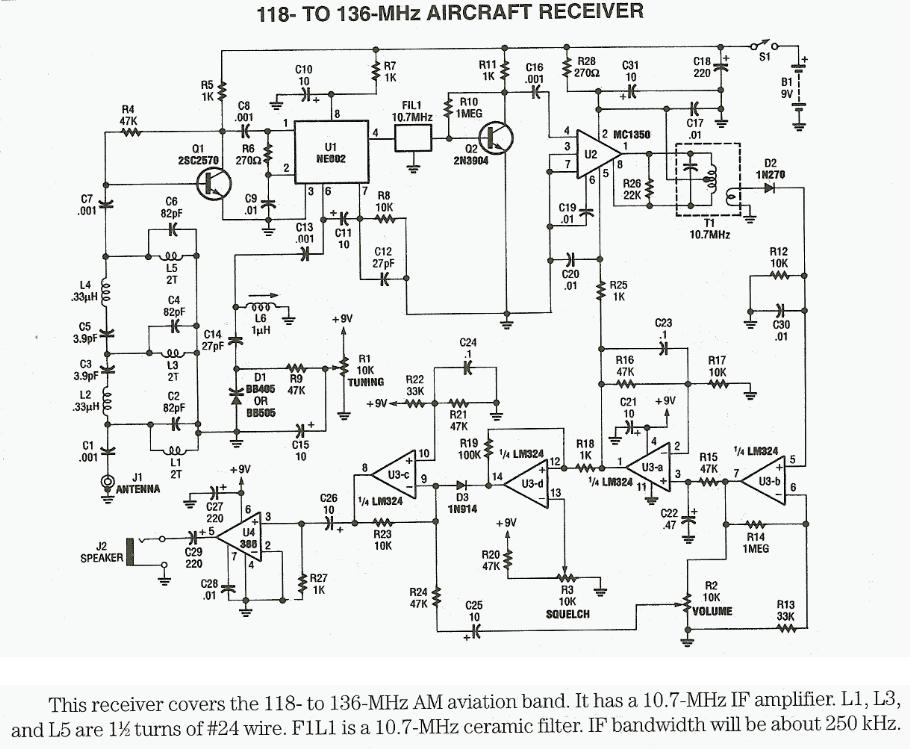
118MHz to 136MHz aircraft receiver - Schematic only, no circuit description __
150mW FM Transmitter - The circuit is identical to the V7 VHF FM Transmitter but with a few small additions. TR1 (BC547) is an inverted Hartley oscillator which based upon an inductor fabricated on the PCB. This makes it megga-stable, and setable. __ Designed by Harry Lythall-SM0VPO
150W FM Transmitter Amplifier - This is 150W FM transmitter amplifier for 88-108MHz band. The amplifier has two stages using BLF244 MOSFET transistor for the first stage which requires 0.5 - 1Watt of RF input to get about 20watts to drive the final stage SD1407 which can push nearly 200 Watts on this design. This design is more or less broadband however I added two variable capacitors after each stage for optimum matching and power output. Make sure the trimmer and the capacitors after the final stage SD1407 are a high voltage types with at least 200V rating. The power on this amplifier can be varied by adjusting the bias voltage using the white pot to the BLF244 MOSFET. I added a zener diode onto the bias supply to protect the transistor from too much bias voltage. __
15dB UHF TV Antenna Booster - This is an UHF band TV antenna preamplifier circuit With 15dB gain to build easily. It is formed based on BF180 UHF Transistor. The first stage is an band pass filter constructed by the C1, CV1, L1, L4, C7 and C3, the second stage is a base-common __
15W FM -transmitter - Building a good fm-transmitter (88-110Mhz) begins with getting a good schematic. You don't have to understand the precise working of the transmitter to build it. But some basic information won't harm. A transmitter alone is, as you probably know, is not __ Contact IQ Technologies
15W Transmitter Power Amplifier 88-108MHz - The power amplifier boosts 88-108MHZ 1-2W FM transmitter's power to 15 W. It includes multi-level low pass filter and has a high conversion efficiency with strong Yi-wave suppression. With good antena expected transmission coverage is at least 15Km. It uses high power 175 MHZ 4A 25W 2SC1972 RF transistor that must to be mounted to heatsink for proper heat dissipation. __
18W FM Transmitter - Here's FM transmitter for commercial FM band that provides 18 watts of power. Since the electronic diagram is too large we decided to divide it into two parts. The first part is the actual FM transmitter while the second part is 18W RF amplifier. The circuit should be built on an epoxy printed circuit board with the upper face components reserved for interconnecting tracks and the bottom solder to the ground plane. If powered by 14V and 2.5A transmitter outputs 15W of power, whereas 18V and 3.5A will provide 18W. BB110 variable capacitor connected to the collector of transistor BF199 adjusts the transmission frequency of the circuit.2K2 potentiometer serves as fine tuning. Once the output frequency is adjusted amplifier variable capacitors must be adjusted for maximum output power one stage at a time. All adjustments must be made with 50 Ohm dummy load connected to the output of transmitter. __
1GHZ Frequency Meter - This is 1GHz frequency counter with 100KHz resolution. Meter is built in around PIC16F84A microcontroller and SAB6456 / U813BS prescaller __ Jan Kolar
1KM Power FM Transmitter - This small power FM transmitter can transmit more than 1 km in good conditions. The modulation can be made so much with a microphone or audio source. Circuit of power fm transmitter is built around 2n2218 transistor. Transmitter coil is 5 turns of enameled 22 AWG wire, with diameter of 1 cm without nucleus. Look at the capacitors that it should be ceramic. The antenna should possess from 15 to 40 cm. For transmission it ties a receiver of FM (radio) in the proximity to half volume in a free frequency (that there is not any radio operating), with a wood or plastic key, rotate the screw of CV to capture the frequency of the transmitter. __
1W FM Transmitter - A very good 1 watt fm transmitter circuit, very easy to build circuit. It has 4 transistors, one is a very stable oscillator, followed by a buffer stage to prevent frequency variation when you adjust the transmitter. Next is a resonance stage and the final stage built with a minimum 1W transistor which must have a heatsink. You must use a LM7805 stabilizer for the oscillator diodes and one LM7809 for powering up the T1 oscillator stage. This will give you a very stable transmitter frequency. __
1W Linear FM Booster - This RF Amplifier is used for boosting small fm transmiters and bugs. It use two Philips 2N4427 and its power is about 1Watt. At the output you can drive any linear with BGY133 or BLY87 and so on. Its power supply has to give 500mA current at 12 Volts. More voltage can boost the distance but the transistors will be burned much earlier than usual. ! In any case do not exceed the 15Volts. The Amp offers 15 dB in the area of 80Mhz to 110 Mhz. L4, L5, and L6 are 5mm diameter air coils, 8 turns, with wire 1mm wire diameter. An easy project, with great results __
1W Linear FM Transmitter Booster with 2N4427 - Here's 1W RF Amplifier is for boosting small fm transmitters and bugs. It use two Philips 2N4427 and its power is about 1Watt. At the output you can drive any linear with BGY133 or BLY87 and so on. Its power supply has to give 500mA current at 12 Volts. More voltage can boost the distance but the transistors will be burned much earlier than usual.! In any case do not exceed the 15Volts. The Amp offers 15 dB in the area of 80Mhz to 110 Mhz. L4, L5, and L6 are 5mm diameter air coils, 8 turns, with wire 1mm wire diameter.An easy project, with great results. __
1W Long Range FM Transmitter - Long range, very stable, harmonic free, FM transmitter circuit which can be used for FM frequencies between 88 and 108 MHz. With good antenna transmitter can cover 5km range. It has a very stable oscillator because it uses LM7809 voltage regulator which is a 9V stabilized power supply for T1 transistor. Frequency adjustment is achieved by using the 10K linear potentiometer. The output power of this long range RF transmitter is around 1W but can be higher if you use transistors like KT920A, BLX65, BLY81, 2N3553, 2SC1970 or 2SC1971. __
1W PLL FM Transmitter - The VERONICA transmitter is a very stable, powerful, and high quality FM emitter. Thanks to a PLL, the output frequency is controlled with DIP switches. Output power is approximatively 1W with a single regulated 13.8v supply ! (see specifications) Features : * High RF output power : 1W * Full 87.5-108MHz range (100KHz increment). * Very stable output frequency : Crystal reference & Phase Locked Loop. * Professional input bandwith (fully RDS compatible ) * No complex tuning needed. * High quality PCB * Full documentation & construction details available __
1W PLL Transmitter with MC145152 - Following 1W PLL transmitter exciter provides stable, low noise operation. Transmitter uses a PLL frequency synthesizer built with MC145152 which covers the FM band in 100kHz steps. The VCO uses MV2109 varicap diode to automatically tune to selected frequency via SW1 dip switch. output stage uses 2N4417 RF power transistor and provides 1W of RF power. With good antenna expected transmission range is 2km. Transmitter may be built on a double sided PCB, with top side copper left mostly undisturbed as a ground plane. The copper is removed only around non-grounded pins. The ground connections can be soldered on the top side, so it’s not necessary to have plated-through holes. __
1W Portable PLL transmitter - This small FM transmitter includes a limiter, a microphone amplifier and a PLL digital tuning. All the parts are placed on one circuit board. The RF power is switchable between 1W and 0, 2W __ Jan Kolar
1W RF Power Amplifier for iPOD Stereo FM transmitters - This project explain how you can build and connect a powerful 1W amplifier to your FM transmitters. A perfect solution for those wishing to listen to their favorite tunes in the car, house, garden, school, campus, party, you name it. Why not share your music with every one else in your city! __
1Watt AM CW Transmitter for 10 Meterband - In this project, you will make a simple 3-stage low-power broadcast-type circuit, using a crystal oscillator integrated circuit and an a collector modulated AM oscillator with amplifier. You can connect the circuit to the an electred microphone or amplified dynamic microphone. Using an electred microphone is shown (in gray) in the diagram below. (no amplified dynamic microphone has a to low output voltage to work. at least 100mv is needed). You could also add a LF preamp stage of one transistor to allow connecting a dynamic microphone directly. You'll see that you can receive the signal through the air with almost any AM radio receiver. Although the circuits used in radio stations for AM receiving are far more complicated, this nevertheless gives a basic idea of the concept behind a principle transmitter. Plus it is a lot of fun when you actually have it working! Remember that transmitting on the 10 meter band you'll need a valid radioamateur license!! A wide range of different circuits have been used for AM, but one of the simplest circuits uses collector modulation applied via (for example) a transformer, while it is perfectly possible to create good designs using solid-state electronics as I applied here (T1 BC557). The transmitter is build as a Colpitts Oscillator with a BSX20 transistor. HF-output of the oscillator is approx.50 mW, depending on the supply voltage of 6 to 15 Volts. This is amplified by the BD135 and brings the power up to approx.1 watt @ 12volts. The transmit frequency is stabilized with the 28Mhz crystal. A slight detuning of approx 1kc is possible when using a 120pF trimmer capacitor for C8. The oscillator signal is taken from the collector of T2 and guided to the input of T3 which output is
lead via an L-filter and low-pass PII filter circuit cleaning up the signal pretty good and ensuring spectral purity. The oscillator is keyed by T1 and the morse key (S). By keying the morse-key T1 is not been used for modulation and is biased, hence lets T2 freely oscillate. __
|