|
125khz Oscillator with Medium Power - This circuit adds even more inverters in parallel to deliver yet more power. The values shown are for 125KHz . . . Hobby Circuit designed by David Johnson P.E.-March, 2002
200Mhz-400Mhz Voltage Controlled Oscillator (VCO) - If you need a clean emitter coupled logic (ECL) type signal between 200MHz and 400MHz this circuit works fine. It uses four voltage-controlled capacitors to change the frequency. . . Circuit by David A. Johnson P.E.-March, 1999
40Khz Burst Laser Diode Driver - Some laser tag or simulated combat games can use this circuit to send short bursts of modulated laser light at the opponent's vest, equipped with a matching light receiver. The circuit operates from three 1.5v cells (4.5v) that should provide enough energy . . . Hobby Circuit designed by Dave Johnson P.E.-June, 2000
Accurate 1hz Generator - Accurate 1Hz squarewave pulses are required in stopwatches and other digital circuits. Here is a low-cost, general-purpose 1Hz signal generator without using a crystal oscillator.230V, 50Hz, single-phase AC mains is stepped...__ Electronics Projects for You
AF Generator - The sinewave generator is based on 4 op-amps which are present in a single TL084 ic. (see fig.1). Op-amps A1 and A2 are connected to the frequency determining RC networks R5+P1a/C1 and R6+P1b/C2, respectively. In my version of the generator, P1 is replaced by a stepped attenuator (dual rotary switch with 12 positions, see above). Moreover, I have included two additional frequency ranges; thus, S1 is in my version a dual rotary switch with 5 rather than 3 positions. __ Designed by W.Mieslinger
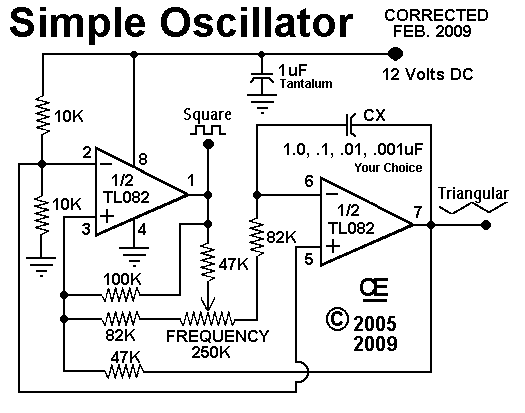
An Oscillator Sawtooth & Square Wave Output - Simple, Single Supply and Works Very well with Minimum Parts Count. __ Designed by G.L. Chemelec
Astable Multivibrator with Very Low Power - This classic circuit draws only 200 nanoamps from a 1.5v supply . . . Hobby Circuit designed by David A. Johnson P.E.-June, 2000
Astable Multivibrators - Multivibrators: an old, well known and boring subject. No - not at all: there are lots of different ways of looking at them and they are not at all what they may seem. __ Designed by Richard Torrens
CMOS
Inverter 125khz LC Oscillator - This circuit uses a single CMOS
inverter to form a series resonant LC oscillator. The values shown set the oscillation at about 125KHz but the other frequencies are possible by changing the main LC values. . . Circuit by David Johnson P.E.-March, 2002
CMOS
Inverter forms a Resonant LD Oscillator - This circuit uses a single CMOS
inverter to form a series resonant LC oscillator. The values shown set the oscillation at about 125KHz but the other frequencies are possible by changing the main LC values . . . Hobby Circuit designed by David A. Johnson P.E.-March, 2002
CMOS
Inverter Parallel LC Oscillator - I have used this parallel resonant LC oscillator circuit countless times. The oscillator frequency is determined by the inductor and capacitor values. I have shown an adjustable inductor to make it easy to set the frequency to a specific value. . . Circuit by David A. Johnson P.E.-March, 2002
CMOS
Inverters Form 125Khz Oscillator - This circuit inverts the LC components so the inductor is grounded. Two inverters are needed to produce the needed oscillation. Again, the values shown set the frequency at 125KHz but can be changed to produce other frequencies . . . Hobby Circuit designed by David Johnson P.E.-March, 2002
CMOS
Nand Gate Forms Gated 125Khz Oscillator - This circuit is uses a NAND gate as an inverter. The gate allows the oscillator to be gated on and off. Again, the values shown set the frequency at 125KHz but can be changed to produce other frequencies. . . Circuit by Dave Johnson P.E.-March, 2002
CMOS
Oscillator, Draws Only 0.5ua - If truly low power oscillators interest you, this circuit draws a mere 2 microwatts (500nA) from a 6v battery. It uses a very inexpensive C-MOS IC to produce a frequency of 2Hz. However, by changing the component values you can push it to 300Hz . . . Hobby Circuit designed by David Johnson P.E.-June, 2000
CMOS
Schmitt Trigger IC Makes VCO - By changing the supply voltage fed to a classic 4584 Schmitt trigger type oscillator, the oscillator frequency can be changed over a range of 50:1. A 74HCU04 inverter is used at the output of the 4584 to maintain a constant TTL logic level signal. . . Circuit by Dave Johnson P.E.-December, 2002
Convert periodic waveforms to square waves - 08/16/01 EDN-Design Ideas - Converting periodic waveforms to square waves is an integral part of extracting a clock signal from data, creating waveform generators, and making timing-pulse generators. Any square-wave-conversion circuit is valuable when the square wave's duty cycle is variable and controllable. Figure 1 shows a circuit that has these attributes and can drive several TTL-compatible loads Design by Ron Mancini, Texas Instruments, Bushnell, FL
ELC signal between 200Mhz-400Mhz - If you need a clean emitter coupled logic (ECL) type signal between 200MHz and 400MHz this circuit works fine. It uses four voltage-controlled capacitors to change the frequency . . . Hobby Circuit designed by David Johnson P.E.-March, 1999
FleaPower Oscillator Consumes only 1 µA - 05/21/98 Design Ideas - (Multiple circuits listed, scroll to find this one) A simple way to make an oscillator is to use a resistor, a capacitor, and a Schmitt trigger (Figure 1a]. However, this circuit uses several tens of microamperes because of the voltage transitions at the Schmitt trigger's input. The CMOS
device consumes almost no power when the input is either high or low. Whenever the input voltage is at an intermediate Design by Yongping Xia, Teldata Inc, Los Angeles, CA
Flexible Outputs from Square Wave Driver - This circuit can produce an output signal ranging from DC to 100KHz. It can source a voltage ranging from 1v to 30v. It can sink a voltage ranging from zero volts to –30v. It can drive up to 200ma of current and can even be switched to a floating tristate . . . Hobby Circuit designed by David Johnson P.E.-July, 2000
Gated 125Khz Oscillator - This circuit is uses a NAND gate as an inverter. The gate allows the oscillator to be gated on and off. Again, the values shown set the frequency at 125KHz but can be changed to produce other frequencies . . . Hobby Circuit designed by Dave Johnson P.E.-March, 2002
Gated Oscillator Emulates a Flip-Flop - 03/16/95 EDN-Design Ideas - The gated oscillator in Fig 1 holds its existing state when disabled rather than being forced high or low-a singular property. Further, you can generate an output at one-half the input frequency if you choose R1 and C so that the oscillator changes state just once when its input goes high. This configuration eliminates a flip-flop. Design by Einar Abell, ADA Instruments, Three Rivers, CA
Harmonic Oscillator - Here is an easy-build high-performance VHF (or UHF?) local oscillator. There are no PCB foil drawings to play with and no coils to wind. There are two 90mm long copper wire inductors needed, but the good news is, you don't have to wind them. The first unit makes an excellent 10mW (+10dBm) exciter to drive a VHF power amplifier __ Designed by Harry Lythall-SM0VPO
Highly Stable Lower Power Oscillator - This circuit works much like the classic 555 timer, but draws only about 1.5 microamps from a 3 volt battery. It is highly stable under varying temperature and supply voltages. . . . Hobby Circuit designed by David Johnson P.E.-May, 2000
LC Oscillator Medium Power 125Khz - This circuit is similar to MEDIUM POWER 125KHZ OSCILLATOR but adds even more inverters in parallel to deliver yet more power. The values shown are for 125KHz . . . Hobby Circuit designed by David Johnson P.E.-March, 2002
Low Power 100khz Light Receiver - By starving a high speed logic inverter for current, this circuit can produce a sensitive 100KHz light receiver circuit, which is immune to ambient light, but only drawing 100 micro amps from a 3 volt supply. . . Circuit by David A. Johnson P.E.-April, 2005
Medium Power 125khz Oscillator - This circuit adds even more inverters in parallel to deliver yet more power. The values shown are for 125KHz. . . Circuit by David Johnson P.E.-March, 2002
Medium Power 125khz Oscillator #2 - This circuit is similar to MEDIUM POWER 125KHZ OSCILLATOR but adds even more inverters in parallel to deliver yet more power. The values shown are for 125KHz.. . . Circuit by Dave Johnson P.E.-March, 2002
Micro Power 40Khz Burst Laser Diode Driver - Some laser tag or simulated combat games can use this circuit to send short bursts of modulated laser light at the opponent's vest, equipped with a matching light receiver. The circuit operates from three 1.5v cells (4.5v) that should provide enough energy. . . Circuit by Dave Johnson P.E.-June, 2000
Micro Power Over-Temperature Alarm - The circuit is powered for years by a single 3 volt lithium battery. It sounds an alarm when the temperature exceeds a certain point. With some minor changes the circuit could also be configured for an under temperature (freeze) alarm. The circuit uses a. . . Circuit by Dave Johnson P.E.-June, 2000
Micropower CMOS
Oscillator, Draws Only 0.5ua - If truly low power oscillators interest you, this circuit draws a mere 2 microwatts (500nA) from a 6v battery. It uses a very inexpensive C-MOS IC to produce a frequency of 2Hz. However, by changing the component values you can push it to 300Hz. . . Circuit by David Johnson P.E.-June, 2000 |