|
1 transistor FM receiver - A printed circuit board for the original circuit is available through FAR Circuits. Ask them for "Andy Mitz's One transistor FM radio printed circuit board". The circuit board must be modified for the improved one transistor radio __ Designed by Andrew R. Mitz 1 Transistor FM Receiver 2 - This radio is sensitive enough to tune 20 stations across the FM band, some with volume high enough to drive a small PM speaker. The ability to tune 88.9 MHz and 89.1 MHz is testimony of its selectivity. The signal-to noise ratio rivals that of the better Walkman type radios. __
1 Transistor Regenerative Receiver - This radio is sensitive enough to tune 20 stations across the FM band, some with volume high enough to drive a small PM speaker. The ability to tune 88.9 MHz and 89.1 MHz is testimony of its selectivity. The signal-to noise ratio rivals that of the better Walkman type radios __ Designed by Phillip Crane mailto:plcrane @ delphia.net
1 Tube FM Tuner - From August 1960 Popular Electronics, it uses a 6C4. I constructed this project as closely as I could to the original. Performance left a lot to be desired! __ Contact blehack @ yahoo dot com
1 Valve FM Receiver with Loudspeaker - Using a single 6DX8, this receiver provides loudspeaker reception of FM stations __ Contact blehack @ yahoo dot com
1 Watt RF Amplifier - This is a universal 1 Watt RF class C amplifier that is ideally suited for low power FM transmitters. input should be at least 100mW to achieve 1W output. it is recommended to enclose the amplifier in a metal case. __
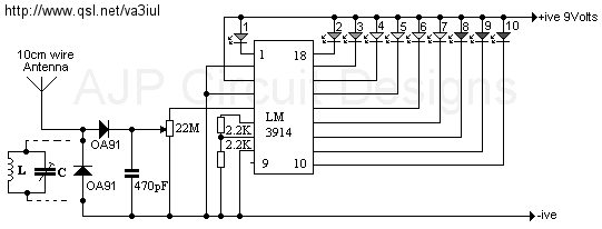
1.3GHz Freq counter LED display, main Design by OZ1DV - The brain of the counter is a PIC 16F84, it does all the display scan, ranges calculation and main counter.
More info about this counter can be found in the Danish HAM mag called "OZ" __ Designed by Thomas Scherrer OZ2CPU
1.3W VHF RF Amplifier 2SC1970 88-108 MHz - This RF power amplifier is based on the transistor 2SC1970 and 2N4427. The output power is about 1.3W and the input driving power is 30-50mW. it will still get your RF signal quit far and I advice you to use a good 50 ohm resistor as dummy load. To tune this amplifier you can either use a power meter/wattmeter, SWR unit or you can do using a RF field meter. __
1.5 GHz PLL Frequency Synthesizer - in order to obtain excellent phase stability between two beams in our experiment, it is preferable to derive them from the same laser. This is a limitation however, if the beams operate at different frequencies. For frequency differences of less than a few hundred MHz, the approach is to split the beam and send it through an AOM. For higher frequencies, we employ an optical phase-locked loop (OPLL) in which the beat frequency between two lasers sent to a feedback loop and locked to a given separation. Since AOMs which operate at 1.5 GHz have become available, we wanted to explore the phase stability of two beams separated by 3GHz (we send the beam through the AOM twice) derived from the same laser source. in order to this, we need a low phase noise signal at 1.5 GHz which is to be amplified to 1W (30dBm) ad sent to the modulator. To achieve this we designed a 1.3GHz to 1.7GHz tunable PLL frequency synthesizer, described below. __
1.5w Power Amplifier - Here we put all the theory to work and present a simple power amplifier module that can be easily built with readily available components. The block diagram of the amplifier is...__ Electronics Projects for You
1.7GHz Freq counter LCD display, main Design by AADE - This ERA amp is mounted on the back side of the wattmeter input card. You need to make a 10 x 10 mm pcb for this amp. All parts are SMD ! the 51R is soldered on the wattmeter input card R16 PAD. The output has about +10 dB attenuation compared to the wattmeter input connector __ Designed by Thomas Scherrer OZ2CPU
1:1 Current Balun using 4C6 core for HF antenna - I like to use Atmel AVR Atmega PIC 16 PIC 16F876 PIC 16F84. Most electronics easy made for the novice and something is for the more experienced. __ Designed by Thomas Scherrer OZ2CPU
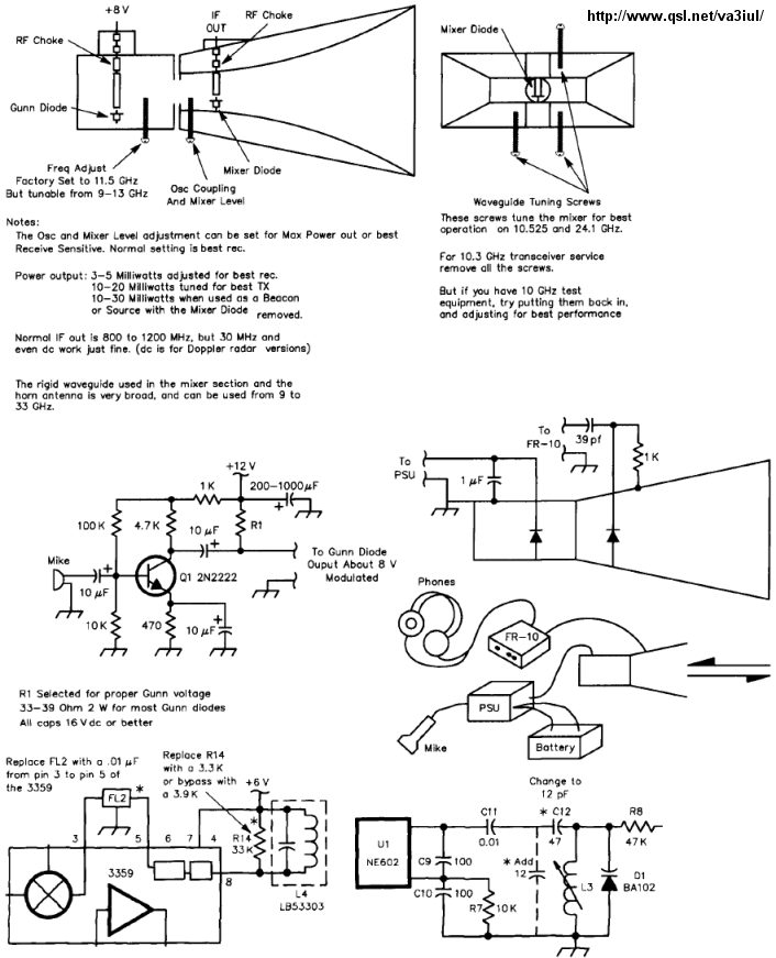
10 GHz Transceiver from a Radar Detector-WA5VJB - Schematic only __ Designed by va3iul
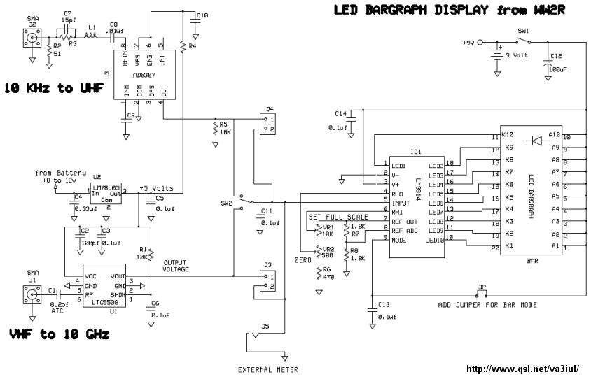
10 kHz to10 GHz LED-Bargraph Power Meter-W1GHZ - Schematic only __ Designed by va3iul
10 meter (28MHz) band RF Amplifier - if you elect to use an antenna tuner, it is extremely important that you understand exactly how to use tuners and what they can and cannot do. A few watts of RF can easily become lost in an incorrectly adjusted antenna matching device. The whole idea of a QRP station is to keep things simple and economical, so I cannot overemphasize the priority of a clean, efficient connection of the amplifier output to a resonant antenna. __ Designed by Guy Roels ON6MU
10 MHz WWV Receiver - For nearly a year, I have been trying to develop a tuned radio frequency (TRF) 10 MHz, WWV, AM receiver. My initial RF stages were common emitter or common source stages with tuned input and output. Despite careful layout, parasitic oscillations plagued these designs and they were discarded. Later, I discovered that only tuning the input of RF stages reduced this tendency towards instability and still provided reasonable selectivity. Different detectors were also tried and evaluated __ Designed by Todd, VE7BPO
10 W Experimental Output & 1 Meter Loop Antenna for 187 kHz Lowfer - This page describes an antenna, a 1 watt final output stage, and a transformation network for radio experiments at 187 kHz __ Designed by Rod Elliott ESP
100 MHz Modulated RF source for FM Band - I needed a frequency reference for tuning up the RS-232 to 100 MHz RF desktop channel adapter elsewhere on this site, when I found this Saronix crystal oscillator in my junk box. A few minutes with VRStudio produced an ATtiny12 to make a tone, even fewer __ Designed by Dick Cappels
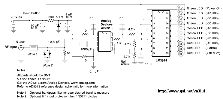
100 MHz-2.5 GHz LED RF Signal Meter AD8313 - Schematic only __ Designed by va3iul
100Khz Crystal Calibrator - There is a great deal of old amateur gear which many amateurs have decided to restore and bring back to life. While much of the early amateur transceivers work just fine they usually lack a digital readout and must rely on analog dials for tuning. The problem of dial calibration is complicated by the non-linear effects of tuning capacitors. This month's circuit is a 100Khz crystal calibrator using an inexpensive microprocessor crystal and CMOS
IC 's which are readily available at Radio Shack. __ Designed by N1HFX
100Khz Low Power Light Receiver - By starving a high speed logic inverter for current, this circuit can produce a sensitive 100KHz light receiver circuit, which is immune to ambient light, but only drawing 100 microamps from a 3 volt supply . . . Hobby Circuit designed by Dave Johnson P.E.-April, 2005
100W FM Amplifier - This Power amplifier is equipped with a bipolar transistor, the famous MRF317 As lots of FM amplifier application , the power transistor is in a C class bias. All the impedance networks (input & Output) have been determined by using the __ Designed by Michel P
100W HF QRO linear Amplifier with Motorola MRF454 - 100W HF Linear Amp - Schematic only, no circuit description __ Designed by © 2001 - YO5OFH, Csaba Gajdos
10BaseT Ethernet 10GHz BPSK link - I don't know where to start on this one as it is still many single bits and bobs floating around that are still lacking other bits to bring the whole thing together. The idea that has emerged so far is to use an Ethernet card with a 10BaseT connection (kept short) to a modem which converts the signal to BPSK. For the moment no synchronization is done, and the whole Manchester encoded data with the link pulse is modulated to 480 MHz band using BPSK. The receiver is to be a simple 70 MHz BPSK demodulator regaining the carrier with a frequency doubler. Receive if is therefor 70 MHz with 40 MHz bandwidth using a converted LNB (more on this later). A UHF / VHF splitter combiner ensures that a single coax cable can be used to connect the RF link part to the modem. The RF link is currently a 45 cm Cassegrain antenna. A feed with OMT splits horizontal and vertical signals. The transmitter is a 10 GHz G3WDG003 up converter by Petra Suckling G4KGC and Charles Suckling G3WDG (find out more here). __ Designed by Edward John Cardew
10-Channel IR Remote Control Receiver - it works with commercial ire remote transmitters and is a snack to build. The channels can be wired for momentary or toggle operation.__ SiliconChip
10GHz RS232 high speed link using FM - The poor man's high speed microwave link. Still working on this. it uses a XC9536 CPLD to link to a serial line, this chip has a built in UART, differential encoder/decoder and a Manchester encoder and decoder. it just fits in a simple 36 block device but I am still battling with the FM decoder which is to be as simple as possible. Favoured project is the DVB IP Gateway so this one has moved to the rear end of my priority list. (Sorry) __ Designed by Edward John Cardew
10-meterband transmitter oscillator for AM or CW with only two transistors - in this project, you will make a simple low-power broadcast-type circuit, using a crystal oscillator integrated circuit and an a collector modulated AM oscillator. You can connect the circuit to the an amplified microphone (no amplified microphone has a to low output voltage to work. at least 100...200mv is needed). You could also add a LF preamp stage of one transistor to allow connecting a microphone directly. __ Designed by Guy Roels ON6MU |