|
3-Minute Closet Light - I have a coat closet by my front door. The thing is very dark at night and really needs some kind of illumination inside. I could hire an electrician to install a light in the closet ceiling and then wire it to a toggle switch outside the door but that would cost me quite a bit of money. . . Circuit by David Johnson P.E.-December, 2011 3-Minute Closet Light #2 - The circuit below is powered by three 1.5v alkaline AA cells. With a finger tap to the pushbutton trigger switch, a cluster of 6 wide angle white LEDs is turned on. The lights remain on for about 3 minutes, then will turn off. The circuit’s standby current is only a few microamps. A set of fresh batteries should last at least 200 light applications. The circuit uses a Schmitt trigger inverter and two transistors. When the pushbutton switch S1 is pressed, the 10uF capacitor C1 is discharged. . . Circuit by David Johnson P.E.-November, 2010
3x3x3 LED Cube - This circuit drives a 3x3x3 cube consisting of 27 white LEDs. The 4020 IC is a 14 stage binary counter and we have used 9 outputs. Each output drives 3 white LEDs in series and we have omitted a dropper resistor as the chip can only deliver a maximum of 15mA per output. The 4020 produces 512 different patterns before the sequence repeats and you have to build the project to see the effects it produces on the 3D cube. __ 555-Timer
4 Channel Timer using Atmel 89C4051 & MAX7219 Display Driver - Easy build 4-channel timer, suitable for energy saving, simple hardware and nice firmware with c coding. Automatic power down mode, simple settings, optional buzzer for sound alarm. __ Designed by Wichit Sirichote
4 Digit Crystal-Controlled Timing Module - Just change the chip to build a stopwatch , a photographic timer, a frequency meter or a programmable down timer.__ SiliconChip
40 LED Bicycle Light 555 Timer 6 Volt - The 555 circuit below is a flashing bicycle light powered with four C, D or AA cells (6 volts). Two sets of 20 LEDs will alternately flash at approximately 4.7 cycles per second using RC values shown (4.7K for R1, 150K for R2 and a 1uF capacitor). Time intervals for the two lamps are about 107 milliseconds (T1, upper LEDs) and 104 milliseconds (T2 lower LEDs) __ Designed by Bill Bowden
40/400MHZ Frequency Counter - Frequency counter is a very important test instrument for Radio Amateurs, especially those who wish to develop or test circuits. There are lots of frequency counters in the market but building one was never so easy & exciting with Microprocessors doing lots of work for us. __
400 kHz-30 MHz Low Noise X-tal Oscillator-DJ2LR - Schematic only __ Designed by va3iul
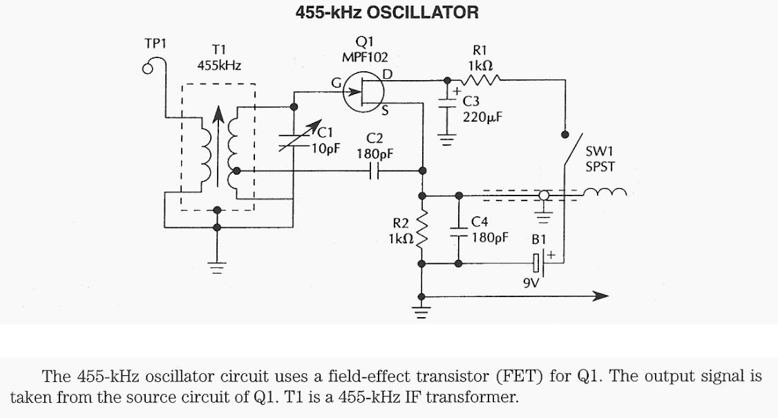
455KHz oscillator using FET & 455KHz IF transformer - The 455-kHz oscillator circuit uses a filed-effect transistor (FET) for Q1. The output signal is taken from the source circuit of Q1. T1 is a 455-kHz iF transformer. __
4-Minute Shower Timer - The sound of running water starts a 4-minute countdown to an annoying alarm. it's easy to build too, as the PC board comes pre-assembled.__ SiliconChip
4-Way Event/Race Anything Timer - it's based on a PIC microcontroller and can time up to four seperate events. You can even get infrared sensors to start and stop the timin__ SiliconChip
5 to 30 Minute Timer - A switched timer for intervals of 5 to 30 minutes incremented in 5 minute steps. __ Designed by Andy Collison
50 MHz Frequency Counter Voltage Meter & SwR/PWR Indicator - This is a successor of the PIC 16C71 4-digit LED f-counter & V-meter. Some hard to find parts used in the previous version, which are out of production for some time, has been omitted. A rather early PIC 16C71 has also been replaced by 28-pin device PIC 16F876 __ Designed by Aleksander Stare
555 (TLC555) Relay Driver - Many integrated circuits have undocumented features or abilities. This is one of them. The TLC555 output (pin 3) can sink a 100mA load to 1.28V. The open drain transistor reset (pin 7) can sink 100mA to 1V. Tying both lines together is permissible because they are logically the same polarity and this potentially doubles the __ Designed by Jim Keith
555 Amplifier - The 555 can be used as an amplifier. it operates very similar to pulse-width modulation. The component values cause the 555 to oscillate at approx 66kHz and the speaker does not respond to this high frequency. instead it responds to the average CD value of the modulated output and demonstrates the concept of pulse-width modulation. The chip gets very hot and is only for brief demonstrations. __ 555-Timer
555 Bistable - Basic circuits and information about this timer/oscillator. Scroll to find Bistable Circuit __ Designed by Jose Pino
555 Christmas Lights - This 555 flasher project is an exception. This is a take-off on the previous Firefly Lights Circuit posting. I had a strip of four tiny PCB’s remaining, so I built them up before __ Designed by Jim Keith
555 DC-AC Inverter - This DC-to-AC inverter schematic produces an AC output at line frequency and voltage. The 555 is configured as a low-frequency oscillator, tunable over the frequency range of 50 to 60 Hz by Frequency potentiometer R4. The 555 feeds its output (amplified by Q1 and Q2) to the input of transformer T1, a reverse-connected filament __ Designed by Tony van Roon VA3AVR
555 Door Ajar Flasher - A magnet is placed on the door and a magnetic reed switch on the door casing so when the door is closed the circuit is disabled. When the door is open, the LED flashes VERY BRiGHTLY—when closed, the circuit is disabled in such a way that it draws virtually no current for maximum battery life. Door Ajar LED Light Schematic Bill __ Designed by Jim Keith
555 Duty Cycle Control - Here is a simple oscillator circuit that varies the duty cycle over a wide range without affecting the frequency. it is a variation of the simple 555 astable oscillator. initially, I told a reader that there was no standard 555 circuit that could do this, but then the grey matter started working. The use of an air-variable __ Designed by Jim Keith
555 Fast Reset Timer - A common problem with on-delay timers is the timing capacitor reset. Typical timers (555 included) rely upon both complete power loss and finite elapsed time to assure that the timing capacitor is fully discharged. if this important detail is ignored, the timeout period is reduced and inconsistent. This 555 timer circuit __ Designed by Jim Keith
555 Go No/Go Tester - This is a more advanced unit with a precise timed testing procedure. R1 (2M2) is same as 2.2 MegOhm. The two timers determine the allowable accuracy for the timer IC under test. Potentiometers P1 and P2 permit ready adjustment for the desired range. __ Designed by Tony van Roon VA3AVR
555 Ignition Coil Driver - This ignition coil driver is a HOT one! From my recollection, it delivers a nastier spark than the legendary Ford Model T ignition coil. The circuit uses an inverted 555 oscillator that is coupled to an ON Semiconductor BU323Z Darlington transistor (350V, 10A) that drives a conventional inductive discharge ignition coil. in __ Designed by Jim Keith
555 LED Flasher - This is a small size LED flasher built with the 555 timer IC that is powered from 2 x 1.5V batteries. The circuit can be used as a flashing metronome, dark room timer, memo-reminder or other similar applications. __ Designed by Popescu Marian
555 Low Voltage Operation - I had heard some stories in the past concerning how poorly the 555 ran below Vcc = 5V, so I embarked on an endeavor to see if I could improve operation. The spec sheet specifies minimum Vcc at 4.5V and I tended to believe it. I set up a simple test circuit and ran each of 5 different bipolar 555 devices while varying Vcc. What __ Designed by Jim Keith
555 makes handy voltage-to-time converter - 02/01/01 EDN Design Ideas: The circuit in Figure 1 is a simple, low-cost voltage-to-time converter using ubiquitous 555 timer chip. You can use IC 's monostable multivibrator as a voltage-to-time converter by connecting analog-voltage input to charging resistor, R, instead of connecting R to VCC. With this modification, Design by J Jayapandian, IGCAR, Tamil Nadu, India
555 Monostable - Basic circuits and information about this timer/oscillator. Scroll to find the 555 Monostable Circuit. __ Designed by Jose Pino
555 Monostable - Use of the ubiquitous 555 timer in monostable mode. __ Designed by Andy Collison
555 on 24v - if you need to operate a 555 on 24v, you will need to reduce the voltage to less than 18v. The following circuits reduce the voltage to 12v. __ 555-Timer
555 oscillator - This is the square wave oscillation circuit which used NE555.555 was developed as the IC for the precision timer. it is compactness (DiP 8 pins) and it is simple composition. it is often used for the timer circuit, the oscillation circuit because of precision well the operation. __ Designed by Seiichi Inoue
555 Pulse Generator - This is a pulse generator with adjustable duty cycle made with the 555 timer IC . The circuit is an astable multivibrator with a 50% pulse duty cycle. The difference from the standard design of a 555 timer is the resistance between pins 6 and 7 of the IC composed of P1, P2, R2, D1 and D2. The diodes D1 and D2 set a definite __ Designed by Popescu Marian
555 Siren Generator - a simple design from 2 555 timers - this is versatile and loud. __ Contact P. Townshend - EduTek Ltd
555 Temperature Controller - You can build a temperature controller circuit with the 555 IC together with a thermistor resistor divider. The advantage is that a well regulated power supply is not needed. The dividing network consists of adjustable resistor R3, thermistor R4 and R5. Temperature Controller Circuit Schematic how does the temperature __ Designed by Popescu Marian
555 Time Delay Relay - This time delay relay circuit is built with IC NE/SE555, produced by intersil which contains a precision timer. Stability to temperature variations is 0.005 %/oC. in the circuit diagram, the IC works as a monostable multivibrator. it is set by operating the key Dr1. With Dr2 you can reset the assembly any time you __ Designed by Popescu Marian
555 Time-Difference-Of-Arrival RDF UNIT - This T.D.O. A. RDF set is built on a Radio-Shack experimenters board. it uses a single 555 timer wired to produce a square wave output at about 500 Hz.1N4007 power ectifier diodes were used in place of PIN diodes to switch between two dipole antennas at a 500 Hz rate. if you substitute another lower voltage power rectifier, __ Designed by Joe Leggio WB2HOL
555 timer - 555 IC could be used for the oscillation circuit, too, but originally, it was developed as the IC for the precision timer. The circuit to introduce on this page is the circuit to make do the operation of the relay in the constant time after pushing a start switch. The circuit outside can be controlled using the point of contact of the relay __ Designed by Seiichi Inoue
555 timer 40khz IR Oscillator - This circuit oscillates two infrared LEDs at 40 khz. To make sure it is transmitting IR light, you can get a little tool from radio shack for about $5. it is a small sheet of plastic about 1" by 3" with a special strip of material, that when exposed to IR light glows (it's actually kinda cool) A way to check for 40khz iR __ Designed by Andy Wilson
555 Timer as an A/D Converter - Measure voltages accurately with a microcontroller using this simple circuit. includes sample program for the Parallax Basic Stamp. __ Designed by Boblick
555 -Timer Based Motorcycle Alarm - Motorcycle Alarm Circuits: This circuit features an intermittent siren output and automatic reset. it can be operated manually using a key-switch or a hidden switch; but it can also be wired to set itself automatically when you turn-off the ignition. By adding external relays you can immobilize the bike, flash the lights etc. Now With Free SiMetrix Circuit Simulation. __ Designed by Ron J.
555 timer based PWM controller for DC Motors & fans - This PWM controller is cheap and easy to build, but has no temperature control and with components shown runs at relatively low frequency. __ Designed by © Madis Kaal
555 timer Design using matlab - Presented here is a Matlab program to design an astable multivibrator of desired frequency and duty cycle using a 555 timer. The aesthetic graphical__
555 Timer Drives Multiple LEDs from One NiMH
Cell - 2-Oct-08 EDN Design Ideas: Using a CMOS
555 timer, you can drive seven high-brightness LEDs from a single 1.25V cell Design by Chuck Irwin, Hendersonville, NC
555 Timer Eliminates LED Driver’s Need for Microprocessor Control - 3-Sep-09 EDN Design Ideas: A timer provide as programming pulses for lower cost than a microprocessor Design by Michael Day, Texas Instruments, Dallas, TX |