|
Single-digit Nixie clock - A while ago I found a Burroughs B-5853 Nixie tube kicking around in the lab and decided that I should put it to good use. Since I only had one of this size, I wanted to make a single-digit display out of it. __ Designed by © 2007 Riad S. Wahby Single-Ended 2A3 Amp - This amp uses a 6C45pI input tube loaded by a 1:1 interstage Transformer (I used the inexpensive model available from Allied Electronics). The 6C45pI is supposedly not rated for more than 200V on the plate, but I have not had any trouble with 300V in this application. You may not wish to follow in my footsteps if you paid a lot for your 6C45pi's __ Designed by Bob Danielak
Single-ended driver for a Circlotron OTL - Originally, this circuit was driving a 6B4G PP output stage. Transformer-coupled, naturally. I started with cap-coupled Mullard splitter using three 4P1L direct-heated loktal pentodes. Not bad at all, but had insufficient gain. Then I tried a plain Loftin-White configuration with a LL1660 interstage (this one is a one-of-a-kind custom 30mA version __ Contact klausmobile @ yahoo.Com
Solid State Power Op-Amp Amplifier - LM675 Amp Schematics, only. This was my minimalist interpretation of the so-called "Gaincard" amplifier. it uses the minimum number of parts I could get away with. All parts are directly soldered to the IC leads for minimal stray inductance. it works and sounds suprisingly good! __ Designed by Bob Danielak
Stereo Push Pull 3CX300A1 Amplifier - The schematic is shown HERE. At some point I will add some detail for this amp, but it is loosely based upon my "Beast" amplifier, referenced elsewhere on this page. __ Designed by Bob Danielak
Stereo Tube Amplifier - The circuit is simple, yet is capable of excellent performance. I designed it specifically for use as an amplifier for the digital sound card in my computer. Audio input can be from any two-channel line level device such as a television, CD player __ Designed by Aaron Cake
The Beast-100 to 300W Push-Pull 3CX300A1 Amp! - This project was inspired by a visit with Eric Barbour, Applications Engineer for Svetlana , in his Portola Valley, CA office. I was in Silicon Valley on other business and decided to pop in to meet face to face. Eric had, in the past year or so, been very supportive of my efforts with my Single Ended SV811-10 Amplifier. During our conversation I mentioned that I tend to keep out of the mainstream when it comes to audio design. This is what originally lead me to try the SV811 and SV572 types over the currently popular tube choices. With that he handed me a pair of 3CX300A1 and said "Whadaya think you can do with these?! " __ Designed by Bob Danielak
The GrampAmp Tube Amplifier - A simple mono vacuum tube audio amplifier. For guitar and mp3 input.__
The House Finch Direct Conversion Tube Receiver - After building the Little Chickadee 6U8A vacuum tube 80 meter CW transmitter project, your author decided that it would be a good idea to build a companion 80 meter tube CW receiver. A direct-conversion design seemed like a good approach since it is fairly simple and is effective for receiving morse code. Not wanting to reinvent the wheel, the internet was searched for vacuum tube direct conversion designs. Surprisingly, no other projects were found. The online projects that were found were either solid state designs or regenerative tube circuits. __ Designed by C. Forrest Cool
The Little Chickadee 6U8A QRP Transmitter - This project involves the construction of a one-tube ham radio QRP (low power) transmitter for the 80 meter or 40 meter band. A single 6U8A tube is used for the RF signal path, it contains a triode and a beam pentode in a 9 pin envelope. Output power is around one watt. One watt may not sound like much power but with a good antenna and an open short wave band, the signal can propagate for hundreds of miles. This transmitter features a waveshaping circuit that produces a CW tone that is free of clicks, this makes it sound very good on the air. __ Designed by G. Forrest Cook
The WB0RIO 6U8A Code Practice Oscillator - This circuit uses a 6U8A triode/pentode tube as the heart of a code practice oscillator (CPO). it is simple enough to be built by a beginner and would be a good introductory project for those who want to experiment with vacuum tubes. The circuit produces a hi-fI sinusoidal output with a wave-shaped envelope for minimal key clicks. These features reduce operator fatigue and make the CPO easy to listen to for extended periods. For contrast, see my solid-state Smooth Tone Clickless CW Sidetone Generator project. __ Designed by G. Forrest Cook
Tube 829 RF power Amplifier - Probably this device has more parts , but indeed it is one of the best output amplifier. it has no problem. it can gives about 400w near 28MHz. The sound level is very high. The modulation level can be adjusting easily by using the 10K pot. Speak to the microphone, the voice will burst in the channel like a thunderbolt. The pot solves many problems. it controls, modulation and output power level. __ Contact IQ Technologies
Tube active crossover - Let me start by saying that i'm not a filter expert. I'vecertainly designed many active filters in my career, but I don't have an understanding of the complex mathematics involved, so i'm basically a cookbook filter designer. I took standard filter design and put in tubes as the active elements. For a very good text about designing active filters, look at this from Texas instruments - "Active Filter Design Techniques", excerpted from "OpAmps For Everyone", also an excellent book. Although this describes filter design using OpAmps, the principles all apply to tube circuits as well. Another good reference is App Note OA-26 from National Semiconductor. __ Designed by Pete Millett
Tube Amplifier Kit - The amplifier kit uses two 11MS8 tubes per channel. The two DC blocking capacitors and the four coupling capacitors are metallized polyester, while Samsung aluminum electrolytic capacitors are used to filter the solid-state power supply. __
Tube Amplifiers - This project is finalized, that means it is no longer experimental. This amplifier, altough limited in output power (20W) , has been designed to give the best listening pleasure. No compromise has been made during components choice: the 845 output triode is one of the best tube available today in that range of power for single-ended applications, the driver stage uses a 300B, a long revered audio tube (note that you must use a WE 300B or a Sovtek 300B). This technical choice has been made in some commercial (like Marantz T1) or amateur __ Designed by puechmor @ mygale.org
Tube Car Stereo Amp - YES, a tube amp in a CAR! ! ! __ Designed by Bob Danielak
Tube curve tracer - The tester is an entirely analog device controlled by a PCI bus industrial DAC/ADC card. As built, it enabling curve-tracing of small single and dual triodes with indirect heating. Dual triodes can be tested each side separately or both sides in parallel. Full tests of pentodes are possible with an external screen grid supply. The design is easily scalable for power tubes (as for Ua/ia limits) , although to drop grid bias below -15V (OpAmp limits) you need to add a special DC amplifier with it's own power supply. Once a set of tube curves is retrieved, the software can estimate operating point, linearity, Gm-mu-Rp curves, etc __ Contact klausmobile @ yahoo.Com
Tube Microphone Preamp - This preamp design started out as a conventional three stage cascade with feedback RiAA equalization. I decided on 6SL7's running into 6SN7's. I figured it would be a good match (electrically and asthetically) for my 2A3 Amp. After thinking it through I thought I might just try passive RiAA. (Even a better match - no feedback! ! !) I noticed a neat RiAA preamp circuit in the back of the RCA Tube Manual RC-19 that used a single 7025 per channel __ Designed by Bob Danielak
Tube Opamps - Photos of an antique analogue computer unit (Soviet, naturally!). __ Contact klausmobile @ yahoo.Com
Tube provides linear tuning - 11/05/98 EDN Design Ideas: (FILE
has many circuits, scroll to this one) Parallel LC circuits that you tune by changing capacitance have a nonlinear frequency-versus-voltage or frequency-versus-shaft-position characteristic. The frequency of an analog-tuned circuit is proportional to the reciprocal of the square root of the tuning capacitance. When you tune a bandwidth that is say, 5% or less of the center frequency, the frequency-versus-capacitance Design by Lyle Williams, Electronic Technical Services, New Orleans, LA
Tube Screamer-based overdrive - Tube Screamer-based overdrive. __ Contact holler @ runoffgroove.Com
Two nixie display clock - My clock building habit is apparently as bad as ever. This time, it was inspired by a stash of Burroughs B5092s, so I needed to vertically align it. Also, since I wanted to make it as small as possible, I wanted to keep nearly everything surface mount, so I abandoned the idea of using 74141s in favor of standard BCD to decimal converters plus some external drive transistors. No need to multiplex since i'm only using two tubes, so this design is actually pretty straightforward. __ Designed by © 2007 Riad S. Wahby
Two Valve 40m CW Transmitter - amateur radio construction projects. circuit only, no description given. __ Designed by Peter Parker
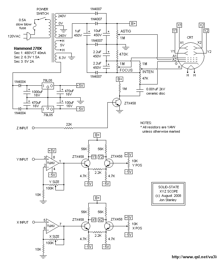
Ultra Simple Circuit CRT Oscilloscope - Schematic only __ Designed by va3iul
Vacuum Tube B+ Delay - This circuit can be added to a variety of vacuum tube devices to automatically delay the application of the high voltage supply until after the tube filaments have warmed up. Vacuum tubes can be damaged or have their lifetimes shortened if high voltage is applied to the tube while the filament and cathode are warming up. The B+ delay is a good fit for devices which use efficient solid state rectifiers. Older tube equipment used slow-warming rectifier tubes or time delay relays to perform this job. Rectifiers and time delay relays generate heat and consume a lot of power. The contacts on time delay relays will eventually burn out. __ Designed by G. Forrest Cook
Vacuum Tube Microphone Preamp/Direct Box Project - from January1997 EQ Column, includes phantom power supply__
Vacuum Tube Opamp Circuit - Published in Glass Audio #3/1995 __ Contact: info @ forsselltech . com
Variable Amplifier Impedance - Figure 1 shows two amplifiers (shown as OpAmps) , with (a) being conventional voltage drive, and (b) is current drive. The output impedances are in the order of zero ohms and infinite ohms in each case (this iS a theoretical discussion at the moment!). The gain will appear to be exactly the same for each into an 8 ohm resistive load, __ Designed by Rod Elliott ESP
VFD (vacuum flourescent display) clock - This is my fifth retro display clock (others: 1, 2, 3, 4) , but the first based on a vacuum fluorescent display. Let's get right down to it. __ Designed by © 2007 Riad S. Wahby
WB0RIO Piglet 6U8A Regenerative Receiver (Tube based) - This project is your author's first attempt at building a regenerative receiver. The "Piglet" name comes from the squealing sounds that regenerative receivers make when the regeneration control is adjusted. The receiver tunes from 5-10 Mhz in the shortwave band it can pick up foreign and domestic AM broadcast stations with ease. The Piglet can receive SSB and CW radio signals in the 40 meter ham band. if you want to use the circuit as a communications receiver, the tuning range should be reduced by using a small-value variable tuning capacitor across a fixed capacitor. __ Designed by G. Forrest Cook
Yaesu Band Decoder schematic - There exist possibilities to transfer an RF signal into a Fibre Optic cable or Dielectric waveguide. There are ways that this can be achieved by using digital or analogue methods. The simplest way is by using analogue modulation. This can done by using AM (Amplitude Modulation) or FM (Frequency Modulation) techniques. __ Designed by Andrew Quinn |