|

|
|
|
|
|
|
|
|
Reversed Battery Polarity |
 |
I received a call from a toy
company. They were puzzled by some field failures they had been having. The
company manager said his engineers assured him that the failures were not due to a design
flaw but due to bad parts, a manufacturing problem or customer abuse. But, the
manager was not so sure. He wanted a second opinion.
He sent me a few good units, a
documentation package and some defective units, which had been returned by some
customers. |
| The 9v battery
powered unit was a pretty simple circuit. Most of the electronics was associated
with a microprocessor. But, I also saw a couple standard CMOS
logic devices.
Looking over the design, I had a hunch. One of the things that I didn’t see in the
design was a way for the circuit to survive a battery polarity reversal. The
electrode terminals of a nine volt battery in particular are easy to switch when trying to
snap them onto the battery clip. Even a second of reversed polarity can be enough to
destroy many logic chips. A fresh 9v battery can easily route an Amp of current
through those circuits. |
| The defective units
did not show any outward sign of damage. I didn’t see any burned components. A
quick measurement with my multimeter did confirm that one or more of the logic gates were
dead. The input protection diodes, internal to nearly all such devices, were indeed open.
To prove my theory, I sacrificed one working unit. I first made sure the device was
in perfect working order. I then reversed the 9v battery polarity and held it onto
the battery clip for about two seconds. I then reconnected the battery to the clip
with the correct polarity. As expected, the device no longer worked. Some kind
of polarity protection circuit was needed for this product. |
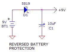
| As the circuit
below illustrates, a simple way to prevent damage from a polarity reversal, is to insert a
diode in series with the DC input. A schottky diode would induce a 0.35v voltage
drop, which in most cases is acceptable for systems running on three or more 1.5v cells.
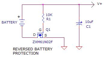
For lower voltage systems, the circuit shown below can be used. It switches on a
transistor, only when the proper battery polarity is used. |
| In conclusion, a
good product design needs to assume that the customer will make mistakes. A common
mistake is to install batteries backwards. A simple polarity protection addition to
the circuit will reduce the number of dissatisfied customers. |
|
|
|
|
|