|

|
|
|
|
|
|
|
|
Battery Charging Generator Starter
(February 26, 2011) |
 |
Wily was
clearing his driveway of snow when he got a call. It came from a company who makes
custom propane fueled electrical generators. Their devices were modified RV
generators specifically designed for backup power for homes off the utility grid.
Instead of producing AC power, as most emergency power generators, the company’s generator
was designed to charge up a large lead-acid battery bank. When the battery voltage
reached a critical point, the generator automatically kicked into operation and ran until
the battery was fully charged.
The company said that for the most part their machines worked fine but they
were having problems with their engine starting mechanism. This engine was started
with a conventional starter motor, which was engaged to a gear on the engine shaft using a
solenoid. The solenoid and motor were powered by a small 12 volt battery. The
caller said that the engine often didn’t start properly. They wondered if Wily had any
suggestions. |
 |
Wily asked a bunch
of questions before deciding to take on the project. The alternator used very
powerful permanent magnets in the rotor. The three phase stator windings were
connected to a bridge rectifier. The output voltage was designed for large 48v
battery banks. The alternator’s speed was controlled by a circuit to first
limit the battery charging current and then later to limit the charging voltage.
A 12v starter motor and solenoid were engaged when starting the engine. A separate
12v battery was mounted next to the engine and was trickle charged from the main
battery bank. The main problems seemed to involve the starter motor and the
solenoid, which engaged the starter motor to the engine shaft. |
|
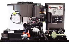
Propane Powered Generator |
|
|
|
Wily gave some thought to this system and wondered if they needed a starter
motor and solenoid at all. He thought that since the starter was causing so many
headaches that perhaps they could do away with the starter motor, 12v battery, solenoid
and gears entirely.
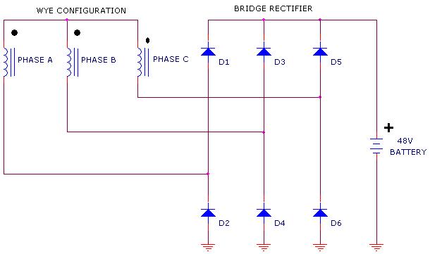
As the drawing below illustrates, the alternator was wired in a three phase
“Y” configuration. By making a few changes, the alternator could be turned into a
very powerful motor. The motor had the advantage of being able to draw current from
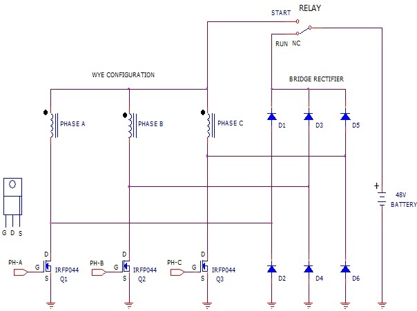
the main battery bank. Using this method, the company’s control system would just
need to activate a relay to switch the battery between the rectifier circuit and a
brushless DC motor configuration. |
|
 |
|
Alternator’s Wye
Circuit |
|
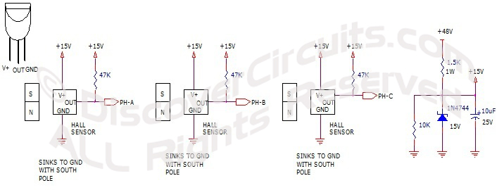
To drive the motor, three powerful MOSFET transistors would be needed.
The drive signals to the FETs would come from three Hall Effect switch devices, mounted in
the motor stator and positioned so the magnets in the rotor would switch the Hall sensors.
The hall sensors would then commutate the motor properly during engine starting.
They only had to apply power to the starter relay for a few seconds to almost guarantee an
engine start.
After a few round of prototypes, the company told Wily that the new
starting system worked well. Starting was smooth and reliable. The company saved
some money by removing the starter motor, solenoid and battery. They kept the pull
starter, which allowed the engine to be started without a battery. |
|
 |
|
Alternator/Motor
Switching |
 |
|
Hall Sensors Used as
FET Drivers |
|
|
|