 |
February 13, 2011
I got a frantic call from a company who builds powerful ultrasonic cleaning
machines. Their machines use banks of 50 watt piezoelectric 40KHz transducers.
Up to 6 can be driven by a single driver board. For years they were doing fine.
Then, for some reason the last batch of boards they were getting from their assembly house
were not working right. The units might work for a while but would then suddenly
stop. In each case one or more of the MOSFET power transistors which made up the
driver circuit would be shorted and the unit’s fuse would be open. They could not
figure out why these units were failing. |
|
|
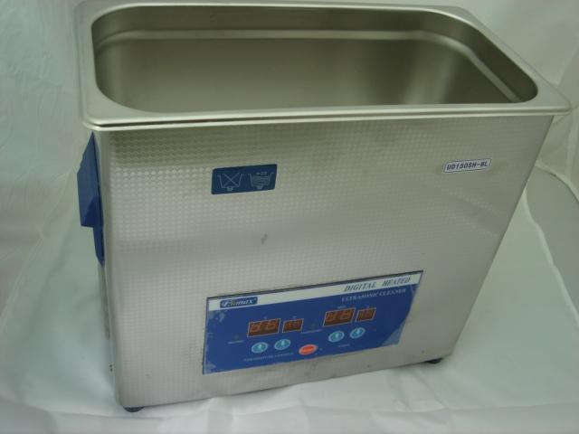
40KHz
Ultrasound Cleaning Machine |
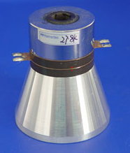
50 Watt 40KHz
Transducer |
 |
 |
The company sent me a documentation package, a cleaning machine, an old
working board and a few of the new boards. At first glance both board types looked
identical. I looked at the schematic. The 40KHz drive signal was created using a
pair of high voltage MOSETs, wired in a “push-pull” configuration. The transistors
drove the primary of a large ferrite transformer. The secondary of the transformer
drove the bank of transducers through a large ferrite pot core inductor. I measured
the inductance of the magnetic parts. Both the primary and secondary of the
transformers on the old and new boards matched. However, the inductance of the
series inductor in the new boards was quite a bit higher. Since this could be a
clue, I dug a bit deeper. The pot core inductance was designed to help match the
impedance of the transformer secondary to the complex impedance of the piezoelectric
transducers. The parallel capacitance of the transducers and the inductance of the
coil formed a series resonant circuit. In theory, the circuit should help generate a
cleaner near sine wave shape waveform.
|
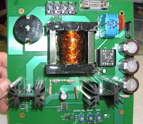
300 Watt 40KHz
Transducer Driver Board |
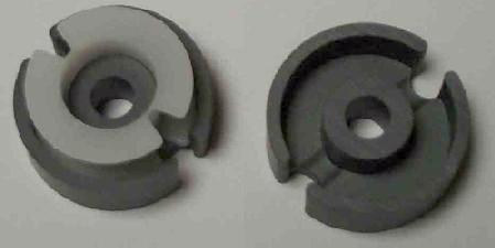
Pot Core with
Nylon Bobbin |
 |
 |
I unsoldered the pot core from both the working board and one of the new
boards. I carefully dismantled the two parts. When I pulled apart the core
from the new unit all I saw was a coil of magnet wire on a nylon bobbon, the two pot core
halves and a nylon screw to hold the assembly together. But, when I took apart the
old unit, out rolled a thin plastic washer slipped between the two pot core halves.
Bingo! The thin plastic washer between the core cups formed a small gap. Gaps are
often used to stabilize an inductance and more importantly in this circuit, helps prevent
core saturation. Every core has a maximum Amp-turns rating. If you exceed that
current, the core saturates and the inductance suddenly drops to a lower level. Now
it all made sense. If the core saturated, the peak current through the two FETs
would quickly spike, enough to exceed their rating and then puff, shorted transistors. I
told the company my findings and asked them to check the rest of the pot cores in some of
the new boards. Sure enough, all the units they checked did not contain the
thin plastic washer. As a final proof, I used an X-Acto knife and cut a piece of
plastic sheet of the right thickness and inserted into the pot core center. I then
re-soldered the now gapped core in one of the new boards sent to me and fired up the
machine. It worked perfectly.
It is too bad that all of these problems were caused by a thin piece of
plastic worth pennies but without it, this expensive piece of hardware would be worthless. |