|

|
|
|
|
|
|
|
|
Motor Speed Controller |
 |
I got a call from one of my old clients.
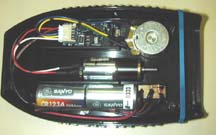
A few years earlier I had designed a brush type motor controller for them, which was used
in a medical product. The motor was powered by two lithium batteries and had a
simple dial type speed control knob, which could set the speed from about 10% to 100% full
speed. Once set, the controller would try to maintain that speed, even as the motor
was loaded down. |
| The
circuit relied on current pulses from the brush commutator to sense the motor speed.
My old client said that they have been having a terrible time with the latest units
produced. They had been using the same motor and same circuit for several years
without any problem. Now, they can’t seem to get the circuit to maintain a constant speed.
The speed would sometimes jump around. |
|
|
| They
sent me a couple units to test. They also sent me one of their old units, which
worked correctly. I noticed that the brush motor was slightly different than the
model that first went into production. When I asked them about this, my client said
that indeed they had changed motor models. The supplier said that the motor had the
same specs but was much cheaper. I suspected that the motor was the root cause of
the problem. |
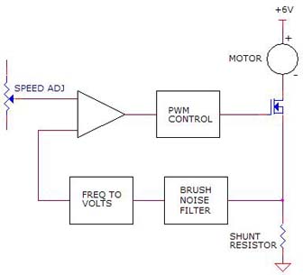
| As
illustrated below, the speed control circuit used a current shunt resistor to monitor the
average motor current and to extract shaft speed information from the pulses produced by
the two motor commutation brushes. The average motor DC was used to control the
motor torque. The brush pulses were filtered to remove the pulse width modulation
signal then converted to a square wave. The frequency of that signal was then
converted to a voltage and used to control the motor speed through a pulse width
modulation (PWM) circuit. |
|
|
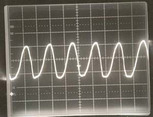
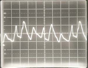
I set up a simple test and captured
the two images below from my oscilloscope. The photo on the left was the brush
pulses from the old motor. The photo on the right was an image of the brush
pulsed from the new motor. Note that the old motor had nice clean repeatable
pulses while the new motor produced erratic pulses. Also note that the new
motor also had some DC level shifting. No wonder the motor speed was bouncing
around.
The existing brush signal filter network on the
motor control circuit did not have enough power to accurately extract the needed
speed information. The medical company would either have to change the control
circuit or they would have to go back to the original motor. After some
prodding from me, they decided to go back to the original motor. As soon as
they made the switch, the problems went away. |
|
| |
 |
|
|
|
| |
Old Motor Brush Pulses |
|
New Motor Brush Pulses |
|
|
|
|
|