|

|
|
|
|
|
|
|
 |
High Power Flashing LED
(February 27, 2010) Wily got an unusual request
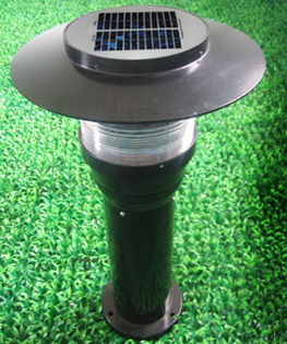
from a caller. The company wanted to use an off-the-shelf solar powered LED path light
but instead of a steady state light, they wanted the thing to flash. The company did not
want to go into detail about the ultimate application but they wanted the light to flash
at a certain rate, a specific duration and be very bright. The kicker was that instead of
flashing a visible light, they wanted this device to flash invisible infrared light. Wily
suspected that the device was going to be used for some kind of military application but
he didn’t push the company for more details. |
The company had already selected the path
light then wanted to use. The device contained two AA size rechargeable NiMH
cells, which
were charged by a solar panel on top of the fixture. The original LED path light used a
yellow LED, but they wanted to flash an infrared LED with a wavelength of 850nm. Could
Wily do it? |
|
|
| Wily gave the
company a rough estimate for designing and building a couple prototype units. They
company agreed and shipped two path light assemblies to Wily to modify.
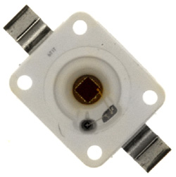
The first thing that Wily had to do was look at the
voltage and current requirement of an 850nm infrared power LED. The SFH4232 LED from
OSRAM Opto looked like it should do the trick. This part had a forward voltage drop
of 1.5v with a current of 1 Amp. However, the data sheet indicated that with a low
duty cycle and a short pulse duration, as much as 2 Amps could be pumped into the
part. At 2 Amps the voltage drop was about 1.7v. This told Wily that a precision
constant current drive would not be needed. He could pick a current a bit above 1 Amp
and let the drop in voltage, as the battery was depleted, serve as a crude current
limiter. |
 |
|
OSRAM 850nm Infrared Power LED |
The client company specified that they
wanted the unit to flash once every two seconds for 25ms. If Wily set the peak LED
current at 1 Amp, that meant that the average current would be 0.5Hz x 0.025s x 1A =
0.0125A. So, if the thing flashed for even 48 hours, with no help from the solar
panel, the Amp-hour capacity of the battery would have to be about 0.6 Amp-hours.
Since a fresh NiMH
cell might have an Amp-hour capacity of 2.5 Amp-hours, and the
device would be turned off during the daylight hours, Wily was satisfied that there
would be plenty of power to do the job. |
 |
 |
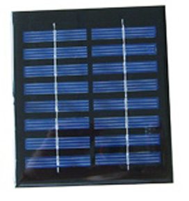
| 8 Solar
Cell Panel |
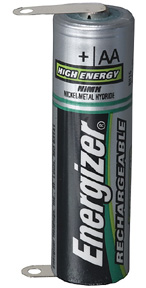
AA NiMH
Cell |
|
Each NiMH
cell puts out 1.2v and would
plunge to perhaps 1.0v toward the end of its charge condition. So, with only two
cells, the available voltage could get down to 2.0v. This should be just enough
voltage to drive the LED, provided Wily was able to come up with a scheme to control
the peak current with very little wasted power. Wily had a few ideas on how to do
this and began drawing up the schematic for the flashing circuit. Wily also inspected
the rest of the path light circuit. |
| As in the original
path light circuit, Wily could use the voltage developed across the 8 cell solar
panel as a nice daylight sensor. He would suppress the LED flashing circuit
during the daylight hours. He noticed that the path light’s solar panel was
linked to the two battery cells using a single diode. There was no fancy charge
control circuit. The limited current and voltage from the solar panel and the
fact that the light would be flashing every night, should keep the battery from
being overcharged. The diode prevented current from leaking back into the solar
panel from the batteries, during the night. Since this was a proof of concept
project, Wily figured that a better battery and charge circuit would not be
needed. Perhaps in the future, he might suggest that the company consider a
lithium ion battery with a smart charger circuit. |
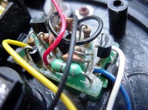
| Wily completed the
path light inspection and removed the main circuit board from each. He took
some mechanical measurements and was satisfied that his circuit could fit into
same slot as the original board. Wily purchased the parts he would need for the
prototypes. His purchase included one green power LED, which used the identical
package as the infrared part. When Wily received the parts, he first inserted
the green LED in a position inside the path light assembly, where he figured it
would produce a wide even illumination pattern. When connected to a DC power
supply, the light from the green LED did indeed generate a nice pattern of
light. With the placement of the LED tested, Wily shifted his focus to the high
pulse current circuit. |
 |
|
Original Path Light Circuit
Board |
|
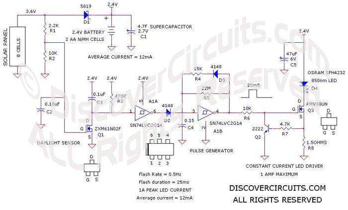
| The circuit that Wily
came up with is shown below. A tiny dual Schmitt trigger inverter IC formed the
pulse generator and the daylight sensor circuit. The circuit produced a positive
pulse, which fed the constant current LED driver circuit. With each pulse, a heavy
1 Amp current pulse was sent through the infrared LED. A second Schmitt trigger was
used in the day/night sensor. The voltage produced by the solar panel when
illuminated by sunlight was used to suppress the pulser oscillator during daylight |
| The LED driver circuit
used a quality n-channel MOSFET with a low channel resistance and a simple current
regulator. The regulator relied the voltage developed across a resistor. When the
voltage reached about 0.6v it was enough to begin turning on a NPN transistor. When
turned on, the transistor reduced the drive voltage on the MOSFET gate. This
negative feedback kept the current set close to 1 Amp. To aid in maintaining
current regulation, by keeping the battery voltage from plunging, Wily also
installed a 4.7 farad supercapacitor across the battery. |
|
 |
|
|
|
|
|
|