|
Simple Circuit BER meter is easy to build - 03/02/00 EDN Design Ideas: General filters are bandpass filters that usually employ bridging couplings between nonadjacent interstage couplings (Reference 1]. This class of filters also includes bridging coupling across filter input and output ports. The implementation of input-to-output bridging already exists for a one-pole filter (Reference 2]. For a two-pole filter, dielectric resonators help achieve input-to-output bridging coupling (Reference 3] Design by Luis Miguel Brugarolas, Sire Sistemas y Redes Telmaticas, Tres Cantos, Madrid, Spain Simple Circuit Easy Parametric & Graphic Eq's Plus Peaks & Notches - if you're into playing with tone controls and notch filters to see how they change the sound out of your effects, you will undoubtedly have built several glops of R's, C's and pots, maybe some L's to make up the tone networks. While this is fun, it's not very flexible. Sooner or later you might wonder if there is a more general solution to messing with tone controls. __ Designed by © 1999 R.G. Keen
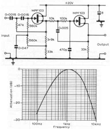
Simple Circuit FET Audio Filter - Schematic only __ Designed by va3iul
Simple Circuit Method of Designing Multiple Order All Pole Bandpass Filters by Cascading 2nd Order Sections - AN27A Presents two methods of designing high quality switched capacitor bandpass filters. Both methods are intended to vastly simplify the mathematics involved in filter design by using tabular methods. The text assumed no filter design experience but allows high quality filters__ Linear Technology/Analog Devices
Single 2.7V Supply 4MHz 4th Order Lowpass Butterworth Filter - Benefiting from low voltage operation and rail-to-rail output, a low power filter that is suitable for antialiasing can be built as shown in this circuit. On a 2.7V supply the filter has a paSSBand of approximately 4MHz with 2VP-P input signal and a stopband attenuation that is greater than –75dB at 43MHz. The resistor and__ Linear Technology/Analog Devices App Note, Jul 20th 2010
Single Op-Amp Bandpass Filter - A bandpass filter passes a range of frequencies while rejecting frequencies outside the upper and lower limits of the paSSBand. The range of frequencies to be passed is called the paSSBand extends from a point below the center frequency to a point above the center frequency where the output voltage falls about 70%__
Single Resistor Tunes Lowpass Filter - 08/21/03 EDN Design Ideas: Any tunable, second-order, active RC-filter section requires at least two thoroughly matched variable resistors. But the lowpass implementation in Figure 1 provide as for wide-range cutoff-frequency control using only a single variable resistor, R. In addition to the resistor, this filter comprises an operational amplifier, IC 2, which serves as a unity-gain buffer; two capacitors, C1 and C2; Design by Vladimir Tepin, State Radioengineering University, Taganrog, Russia
Single Supply 10MHz Lowpass Filter Features the LT1819 Op Amp & Adjustable Bandwidth Up to 20MHz - Low noise, low distortion LT1819 circuit trades parts count and components sensitivity for an adjustable bandwidth - up to 20MHz Diff in diff out circuit. Measured signal-to-noise plus distortion for LT1819 circuit is 71.5dB, just a little nosier than the fixed bandwidth LT6600-10 filter differential filter. __ Linear Technology/Analog Devices App Note, Jul 2, 2012
Single Supply, Micropower, Second Order Lowpass Filter with 60Hz Notch - The first section is a standard low-pass filter with Fc=40Hz. The second section is a notch filter tuned to eliminate 60Hz mains pickup from the signal. __ Linear Technology/Analog Devices App Note, Jun 21, 2011
Sixth-Order Butterworth Low-Pass Filter - Low-pass filters are widely used in the audio domain. Their most important application is in communication receivers and communication audio circuitry. These filters, when used for audio communications, start attenuating frequencies__ Electronics Projects for You
Source resistance & noise considerations in Amplifiers - This App Note demonstrates how a CMOS amplifier is the best choice when a high source resistance is used and noise is the only concern. __ Application Note -- 05.01.2012
SSB AF Filter - This is a simple filter that restricts the LF response a little as well providing quite a heavy HF roll-off. The prototype has enhanced a Yaesu FT101B that was only fitted with an AM iF filter. The IC is an LM358. __ Designed by Harry Lythall-SM0VPO
Subsonic/ Rumble Filter - A 36dB/octave 17 Hz high pass filter to remove ultra low frequencies __ Designed by Rod Elliott ESP
Switched-capacitor IC forms notch filter - 09/30/99 EDN Design Ideas: You can use a switched-capacitor lowpass filter (LPF]to implement an inexpensive notch filter (Figure 1a]. The internal architecture of the IC (Figure 1b]includes summing nodes similar to those nodes that analog-signal-processing stages use for feedback-error generation. The IC lowpass-filters the quantity ViN2VCOM and adds VOS at the output. In other words, Design by Luca Vassalli, Maxim Integrated Products, Sunnyvale, CA
TL081 4 Order Filter - Filters with high orders are designed usually with 2 or more cascaded sections. This order 4 filter need only one OA IC , so we can achieve lower distorsions, lower intermodulation … Resistors values represent the load on the OA output, the maximum TL081 load is 2kΩ. R1-R4 build a 2.5kΩ impedance and so the external __ Designed by Popescu Marian
Tow-Thomas (TT) Second Order Bandpass inverting - Schematic only, no text included__
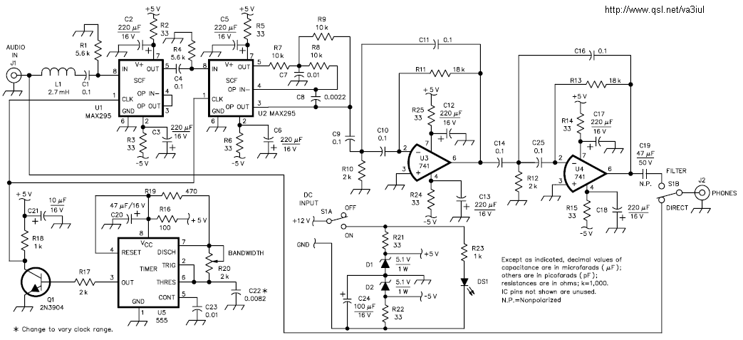
Tunable Audio Filter - Schematic only __ Designed by va3iul
Twin-T Second Order Bandpass inverting - Schematic only, no text included__
Twin-T Second Order Highpass non-Inverting filter - Schematic only, no text included__
Ultra Pure 125kHz Sine Wave Signal Source - For some RFID systems operating at 125KHz, a very low distortion signal source reference is needed. The circuit shown on this page produces a 10-volt peak-to-peak signal into a 50-ohm load, with a distortion of only 0.01% . . . Circuit by David Johnson P.E.-February 11, 2002
Unique Applications for the LTC1062 Lowpass Filter - AN24 Highlights the LTC1062 as a lowpass filter in a phase lock loop. Describes how the loop's bandwidth can be increased and the VCO output jitter reduced when the LTC1062 is the loop filter. Compares it with a passive RC loop filter. Also discussed is the use of LTC1062 as simple bandpass and band stop filter. __ Linear Technology/Analog Devices
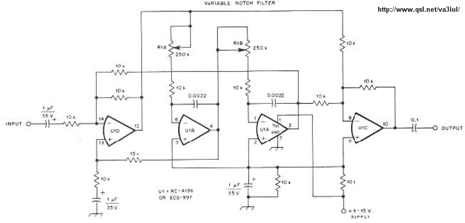
Variable Audio Notch Filter-K4VIZ - Schematic only __ Designed by va3iul
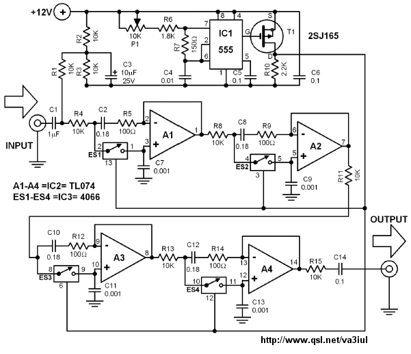
Variable CW Bandpass Filter - Schematic only __ Designed by va3iul
Variable notch filter with both high & Low pass filters - A variable notch filter with both high and low pass filters. __ Designed by Andy Collison
Wideband filter uses image parameters - 26-Oct-00 EDN Design Ideas: You can design various lowpass and highpass filters using image parameters (Reference 1 and Reference 2 ]. By cascading a highpass and a lowpass filter. PDF has several circuits, please scroll to find this one. Design by Richard M Kurzrok, RMK Consultants, Queens Village, NY |