|
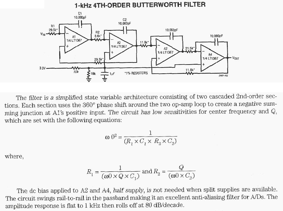
1KHz 4th order Butterworth filter using LT1367 quad operational Amplifier - The filter is a simplified state variable architecture consisting of two cascaded 2nd-order sections. Eaqch section uses a 360 degree phase shift around the two op-amp loop to creat a negative summing junction__
2 GHz-7 GHz Wideband BPF - Schematic only __ Designed by va3iul
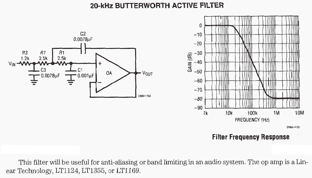
20KHz Butterworth active filter - This file will be usful for anti-aliasing or band limiting in an audio system. The op opm is a Linear Technology, LT1123, LT1355, or LT1169__
24 dB/Octave 2/3-Way Linkwitz-Riley electronic crossover - Linkwitz-Riley alignment. This is a very nice crossover, Rev-B boards now available __ Designed by Rod Elliott ESP
29.85 MHz Bandpass Filter Schematic - Schematic only, no circuit description __ Contact Dale Heatheringtondale111 @ wa4dsy.net
29.85 MHz Notch Filter Schematic - Schematic only, no circuit description __ Contact Dale Heatheringtondale111 @ wa4dsy.net
300 Hz-3 kHz Microphone Filter - Schematic only __ Designed by va3iul
3Khz Filter Audio Amplifier - This circuit is the audio amp section for a complete optical transmitter. The circuit amplifies and filters the voice audio signals from an electret microphone. The circuit is described in more detail in . . . Hobby Circuit designed by Dave Johnson P.E.-June 04, 2000
3Khz Low Pass Filter Plus Audio Amp - This circuit uses a switched capacitor filter IC from National Semiconductor to filter signals with frequencies higher than the 3KHz needed for voice audio. The schematic includes an audio amplifier that is designed to drive a standard audio head phone . . . Circuit by Dave Johnson P.E.-June 04, 2000
3rd Order Filter-Using Model 425 - No description, just schematic - OpAmps Lab inc is the manufactor ofAmplifiers (Video / Audio / Distribution / Microphone / Equalization / Line / VCA / Power) , Switchers (Routing / Assign / Matrix) , Mult (Press) (Network-Feed) Boxes, Audio Transformers, Oscillators, Power-Supplies, Custom Sub-Systems. __ Application OpAmps Lab Inc.
40dB Audio Notch Filter - Schematic only __ Designed by va3iul
440 Hertz Peaked Low Pass Audio Filter Experiments - At audio frequencies, low pass filtering can go a long way to improving CW and beacon reception. It has a been a long time since I built one and therefore decided to experiment with some designs using the 5532 op amp __ Designed by Todd, VE7BPO
4th Order Butterworth filter schematic & calculator - This calculator will design a two-way fourth-order Butterworth crossover network for you. If you don't understand what any of the terms mean, click here for help. __ CarStereo.com c/o Online Connexions, Inc.
60Hz Notch Filter - High input impedance amplifiers are ideal for buffering high impedance networks. Here a twin-T notch filter is shown to reject 60Hz signal content by more the 60dB. Small size, low valued capacitors can be used at such a low frequency with high valued resistors when using a CMOS op amp__ Linear Technology/Analog Devices App Note, Mar 16th 2010
60-Hz, High-Q notch filter - This high-Q notch filter is based on the "Twin-T" design. It produces a very deep notch in the response curve at about 59.7 Hz. This is useful to remove 60-Hz hum and noise from audio recordings or live performances. Response is down over -60db at the center point.
__ Designed by Len Galasso
78 RPM & RIAA Phono Equaliser - MultI Standard 78 RPM and RiAA Phono Equaliser handles all "standards" __ Designed by Rod Elliott ESP
8-Bit Microcontroller Implements Digital Lowpass Filter - 01/24/08 EDN Design Ideas: A simple assembler routine fits a digital lowpass filter into a microcontroller Design by Abel Raynus, Armatron International, Malden, MA
900 MHz Trisection Microstrip BPF - Schematic only __ Designed by va3iul
A Differential Input-to-Single-Ended Output Amplifier - This circuit shows a circuit for converting a differential input to a single-ended output. For a gain equal to one (R1 = R2 = 604W and VOUT = V2 – V1) the input referred differential voltage noise density is 9nV/rtHz and differential input signal-to-noise ratio is 80.9dB with 0.2VRMS input signal in a 4MHz noise bandwidth. __ Linear Technology/Analog Devices App Note, Jul 2, 2012
A Simple Circuit Method of Designing Multiple Order All Pole Bandpass Filters by Cascading 2nd Order Sections - AN27A Presents two methods of designing high quality switched capacitor bandpass filters. Both methods are intended to vastly simplify the mathematics involved in filter design by using tabular methods. The text assumed no filter design experience but allows high quality filters__ Linear Technology/Analog Devices
A Single-Ended Input to Differential Output Amplifier - This circuit shows a circuit for generating a differential signal from a single-ended input. The differential output noise is a function of the noise of the amplifiers, the noise of resistors R1 and R2 and the noise bandwidth. For example, if R1 and R2 are each 200W, the differential output voltage noise density is 9.5 nV/ÖHz and in a 4MHz noise bandwidth, the total differential output noise is 19mVRMS (with a low level 0.2VRMS differential signal, the signal-to-noise ratio is an excellent 80.4dB). __ Linear Technology/Analog Devices App Note, Jul 2, 2012
Active 2nd Order Filters - The figures below illustrate using OpAmps as active 2nd order filters. Three 2nd order filters are shown, low pass, high pass, and bandpass. Each of these filters will attenuate frequencies outside their paSSBand at a rate of 12dB per octave or 1/4 the voltage amplitude for each octave of frequency increase or decrease outside the paSSBand __ Designed by Bill Bowden
Active Audio BPF 1kHz Bandwidth - Schematic only __ Designed by va3iul
Active bandpass filter with TDA2320A - Ham Radio - Other __ Designed by Guy Roels ON6MU
Active BPF 741-WA5SNZ - Schematic only __ Designed by va3iul
Active Filter Has Wideband Tuning Range - 03/28/96 EDN Design Ideas: You can use the basic building block of Figure 1and high-speed analog components to build a second-order lowpass variable-frequency filter with excellent phase linearity (Figure 2]. Figure 1’s filter section includes a Miller integrator followed by a variable-gain amplifier with overall feedback resistor R2. The overall dc gain is the ratio of R2 to R1. This circuit has a transfer[Rea Schmid, National Semiconductor, Comlinear Products Group, Fort Collins, CO] Design by Rea Schmid, National Semiconductor, Comlinear Products Group, Fort Collins, CO
Active High Pass Filters - This is a collection of inverting and non-inverting active high pass filter circuits. I included one, two three, four and six pole filter circuits. You can change the component value ratios shown to achieve any frequency cut-off you may need . . . Hobby Circuit designed by David A. Johnson P.E.-February 11, 2002
Active Low Pass Filter Designs - This is a collection of inverting and non-inverting active low pass filter circuits. I included one, two three, four and six pole filter circuits. You can change the component value ratios shown to achieve any frequency cut-off you may need . . . Circuit by David Johnson P.E.-December 10, 2000
Active-filter & oscilloscope inspect a Class D Amplifiers output - 12/01/06 EDN Design Ideas: Ease debugging of bridge-output pulse-width-modulated audio amplifiers with this circuit Design by John Guy, Maxim Integrated Products Inc, Sunnyvale, CA
Adjustable 60Hz Filter - On this page three adjustable notch filters configurations are shown. They can be used in your small pre-amp or amplifier project to filter out any HUM at 50 Hz (European) or 60Hz. By substituting the capacitors values in the bridge other frequencies can be used. All op-amps configuration requires a +/- voltage supply which can easily provided with a voltage divider made of two. __ Designed by © Laurier Gendron, Burnaby, B.C., Canada.
Adjustable Audio Notch Filter - A variable notch filter with both high and low pass filters. __ Designed by Andy Collison
Adjustable filter provides lowpass response - 03/01/01 EDN Design Ideas: You can configure simple lowpass filters as pI sections with nominal three-pole, 0.1-dB Chebyshev response to provide a moderate amount of stopband selectivity. You can put four of these filters into one enclosure and then select discrete-filtering steps by using toggle switches. Manufacturers of commercially available stepped attenuators and adjustable baseband Design by Richard Kurzrok, Queens Village, NY
Adjustment Free Inclinometer operates on 27V - 4/24/97 EDN Design Ideas: The circuit in Figure 1 is an inclinometer (tilt-measuring circuit] in which the sensor is filled with liquid electrolyte. Acting like a potentiometer, this sensor produces a voltage proportional to the tilt on the center electrode. Because the liquid is subject to electrolysis, the sensor must have an ac-forcing voltage with an average dc component of zero Design by John Wettroth, Maxim Integrated Products, Sunnyvale, CA
Akerberg-MoSSBerg (AM) Second Order Bandpass inverting - Schematic only, no text included__
Akerberg-MoSSBerg (AM) Second Order Highpass inverting filter - Schematic only, no text included__
Analog Filters for Data Conversion (ADC filter) - Figure 3-7 shows a block diagram of a DSP system, as the sampling theorem dictates it should be. Before encountering the analog-to-digital converter, __ Designed by Steven W. Smith, Ph.D.
Applications for a DC Accurate Lowpass Switched-Capacitor Filter - AN20 Discusses principles of operation of LTC1062 and heLPFul hints for its application. Various application circuits are explained in detail with focus on how to cascade two LTC1062s and how to obtain notches. Noise and distortion performance are fully illustrated. __ Linear Technology/Analog Devices
Audio Amp 3Khz Filter - This circuit is the audio amp section for a complete optical transmitter. The circuit amplifies and filters the voice audio signals from an electret microphone. The circuit is described in more detail in . . . Circuit by David A. Johnson P.E.-June 04, 2000
A-weighting filter from an old Ampex service manual - This filter circuit must be driven with low impedance output and the putput of this circuit must be connected to very high impedance input. Second issue for the circuit is that, properly loaded, the circuit describe has about a 12.4 dB insertion loss normalized at 1 kHz (A weighting, in fact, requires a "gain" of about 1.3 dB at 2.7 kHz or so). This insertion loss must be accounted for when used as the original poster describes. __ Designed by Tomi Engdahl |