|
 |
DiscoverCircuits.com -- Hobby Corner
Last Updated on:
Friday, September 20, 2013 05:49 PM
Hobby Circuits'
Category List
The contents &
graphics of Discovercircuits.com are copyright protected.
LINKING to Dave's circuits is permitted but DO NOT COPY any files to your WEB
SITE server |
|
|
|
More
Alarm
Circuits
Current Monitors
Testers |
|
Clip-on AC Current Indicator
Circuit
Pump Motor Monitor |
Several times over the last few years I have received calls from people looking for
a simple circuit that would tell them when a sump pump or water well pump motor was
running. These people told me that the electrical circuits that turn on and
off the motors were frequently inaccessible, often below ground, making it difficult
to know if the motor was running or not. What they wanted was a simple way to
let them know when the motor was on or off, without wiring something into the 120vac
or 240vac power supply. At the time I didnít have a ready circuit for them but
I put the requirement into my subconscious and let my mind work on the problem for a
while. After some thought, I came up with the solution described below. |
|
|
|
|
The traditional method for determining
if a motor is running or not is to measure the current flowing through one of the
wires supplying power to the motor. When the motor is off, the current should
be near zero and will jump to the running current when the motor turns on. The
classic sensor for measuring AC current is a current transformer. In a typical
AC current transformer configuration, one of the wires carrying current to the motor
would be routed through the transformer with the one wire forming a single-turn
primary. The magnetic field produced by the current flowing through the wire
induces a voltage in the secondary winding of the transformer, proportional to the
current. The output voltage of the transformer would then be connected to a
circuit, which would activate a switch, whenever current was drawn by the motor.
However, this single wire connection is often difficult and can be dangerous for a
novice to wire into an electrical system. The installer would have to cut into
the power cable to expose one wire or find an exposed single wire somewhere else,
perhaps inside the circuit breaker box. |
Clamping a typical current meter, using a current
transformer probe, over the whole three wire power cable will result in a zero current
reading, since the field produced by the return wire, which is also inside the cable,
will be canceled by the magnetic field of the supply wire. So, how do you detect
the current? The solution is to rely on the fact that the two wires carrying
current inside the cable are not perfectly in parallel with each other. A small
coil, acting like a transformer, placed against one wire, will pick up more of its field
and less from its neighbor. Although the signal produced by the coil will be
small, enough can be collected to indicate if the motor is drawing current or not.
When connected to a sensitive circuit, a simple monitoring device can be produced.
The user just has to find a suitable place to clamp the box containing the monitoring
circuit to the outside jacket of the power cable, supplying current to the motor. |
| I
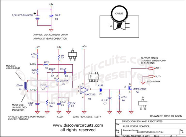
chose to power the monitoring circuit with a small battery. With a simple battery
supply, there is less a user has to worry about. Using modern components, I was
able to keep the current consumption to a very low level. A small 3v lithium
battery cell will power the circuit for about 5 years. The two wires connected to
the circuitís transistor switch can be used to turn on a light or noise maker, located
some distance from the monitoring box. |
| The
circuit uses a small unshielded 100mH inductor as a current transformer. The
voltage generated by the coil is fed to a single transistor circuit, which is configured
as a high gain, low frequency amplifier. The circuit has a gain over 100.
The output of the amplifier is connected to a voltage comparator. The DC bias
voltages at the input of the comparator set the sensitivity of the signal from the
amplifier at about 10 millivolts. This should be sufficient for most applications.
If the coil is placed properly against the outside of the power cable, a current of
100ma AC should be sufficient to activate the circuit. The output of the
comparator is a pulse train equal to the 50Hz or 60Hz power line frequency. A
simple diode rectifies the pulses and produces sufficient DC voltage to turn on the
transistor Q2. The transistor acts as a switch, which closes when the circuit
detects motor current flowing through the power cable. |
| If
the user wishes to power an indicator light from the same 3 volt battery, he should use
a flashing LED circuit, such as the one shown below. This type of circuit will not
tax a small battery. Of course, the user can increase the battery size if desired.
The circuit will work fine from two 1.5 volt AA cells. |
|
|
Click on Drawing Below to view PDF version of Schematic |
|
 |
|
|
|
More
Alarm Circuits
Current Monitors
Testers
Hobby Circuits'
Category List
eMail David A.
Johnson, P.E. about this circuit |
|
|