|
0.3V Crystal Oscillator with Buffered Output - Circuit Ideas for Designers App Note__ Advanced Linear Devices, Inc
0.5V Crystal Oscillator with Output Buffer - Circuit Ideas for Designers App Note__ Advanced Linear Devices, Inc
10 MHz oscillator - This circuit can oscillate up to 10 MHz at VDD 3-15V. __
1 Second Time Base from Crystal Oscillator - The schematic above illustrates dividing a crystal oscillator signal by the crystal frequency to obtain an accurate (0.01%) 1 second time base. Two cascaded 12 stage counters (CD4040) form a 24 stage binary counter and the appropriate bits are gated together to produce the desired division. Using a crystal of some even multiple of 2 is desirable so that one stage of the counter automatically toggles every second which eliminates the need for the NAND gate and reset circuitry, however the circuit below illustrates using a crystal which is not an even multiple of 2 and so requires additional __ Designed by Bill Bowden
10 KHz VFC uses Charge Pump Variation - 04/09/98 EDN-Design Ideas - (Several circuits included, scroll to find this one) A diode-capacitor charge pump is the starting point for many voltage-to-frequency-converter (VFC] designs. The circuit in Figure 1 uses a variation on that classic theme to achieve linearity less than 0.05%, micropower operation of approximately 10-�A total draw from a 5 to 36V rail, and bipolar-input capability Design by Stephen Woodward, University of North Carolina, Chapel Hill, NC
10 MHz GPS Disciplined Oscillator (GPSDO) - A unique feature of the Rockwell/Conexant/Navman Jupiter GPS engines is that they have a 10 kHz output, synchronized to GPS time. So, with a few additional components one can phase lock a 10 MHz VCXO to the 10 kHz, and then have a simple low cost frequency standard with surprising performance __ Designed by James Miller G3RUH
10 Second Ultra Lower Power Oscillator - This circuit works much like the classic 555 timer, but draws only about 1.5 microamps from a 3 volt battery. It is highly stable under varying temperature and supply voltages. . . Circuit by David A. Johnson P.E.-May, 2000
100Khz Low Power Light Receiver - By starving a high speed logic inverter for current, this circuit can produce a sensitive 100KHz light receiver circuit, which is immune to ambient light, but only drawing 100 microamps from a 3 volt supply . . . Hobby Circuit designed by David Johnson P.E.-April, 2005
10MHz GPS disciplined frequency standard - This is the support page for the GPSDO described in the RSGB magazine RadCom for March 2008. As this has become one of those never-ending projects, I have decided to start a web-page dedicated to this project and GPSDOs in general __ Designed by EI9GQ homebrew radio
125Khz LC Oscillator - This circuit adds more inverters in parallel to deliver more power. It is similar to CMOS
INVERTERS FORM 125KHZ OSCILLATOR. Please note that the values shown are for 125KHz.. . . Circuit by David Johnson P.E.-March, 2002
125KHZ Medium Power Oscillator - This circuit is similar to MEDIUM POWER 125KHZ OSCILLATOR but adds even more inverters in parallel to deliver yet more power. The values shown are for 125KHz . . . Hobby Circuit designed by Dave Johnson P.E.-March, 2002
125Khz Oscillator from CMOS
Inverters - This circuit inverts the LC components so the inductor is grounded. Two inverters are needed to produce the needed oscillation. Again, the values shown set the frequency at 125KHz but can be changed to produce other frequencies. . . Circuit by David A. Johnson P.E.-March, 2002
125khz Oscillator with Medium Power - This circuit adds even more inverters in parallel to deliver yet more power. The values shown are for 125KHz . . . Hobby Circuit designed by David Johnson P.E.-March, 2002
125Khz Ultra Pure Sine Wave Signal Source - For some RFID systems operating at 125KHz, a very low distortion signal source reference is needed. The circuit shown on this page produces a 10-volt peak-to-peak signal into a 50-ohm load, with a distortion of only 0.01% . . . Hobby Circuit designed by David Johnson P.E.-February, 2002
13.8V 30-40A Power Supply - Schematic only, a powerful power supply for my amateur radio equipment using four HEX FET transistors for regulation. Text can be found at: http://www.agurk.dk/bjarke/Projects/PowerSupplyFET/PowerSupplyFET.htm __ Designed by Bjarke Korsgaard
1381-based - Type 1 (Voltage Controlled) Solar Engine - Two simple solar engine designs using a 1381* voltage discriminator. __ Designed by Wilf Rigter
175Khz Inductive Pulse Receiver - This circuit is discussed in more detail in the Experimenters Journal. The receiver’s six inch diameter coil detects the ring signal from the above transmitter and use a single NPN transistor to provided enough amplification for the signal to be easily viewed on an oscilloscope. . . Circuit by David Johnson P.E.-June, 2000
1-IC Forms Precision Triangular-Wave Generator - 04/08/10 EDN-Design Ideas - Generate a triangular wave for testing other circuits. Design by Akshay Bhat, Maxim Integrated Products Inc, Sunnyvale, CA
1kHz precision sine generator using PIC - Using a 16F628 to generate an accurate 1kHz sine in software for calibration and test use __ Designed by Roman Black
1kw Sine Wave Inverter - An inverter provides power backup for mains-based appliances in the event of a power failure. Most of the inverters available in the market have complicated circuit design and are not very...__ Electronics Projects for You
2 Stage Chaotic Colpitts Oscillator for the UHF range - Chaos in the Colpitts oscillator was first reported at the kilohertz frequencies [1]. Later the circuit was investigated in the high frequency (HF: 3 to 30 MHz) range [2, 3]. Chaotic oscillations were demonstrated. __
2 Transistor Atomic Frequency Standard - Pretty ambitious title, wouldn't you say? Well, follow the reasoning: If you lower the voltage on the two-transistor flasher to 1.5 volts, the loop gain drops too low for sustained flashing. (See the circuit below.) But, the circuit is highly regenerative and only needs a very tiny push to get it going. By adding a short wire, only a few inches, to the PNP base, the circuit will be triggered into oscillation by the AC electric field from the electrical power (50 or 60 Hz in most places) __ Contact: Charles Wenzel of Wenzel Associates, Inc.
2.4MHz White LED Step-Up Converters with Built-In Schottky in ThinSOT - Switching Regulator__ Linear Technology/Analog Devices
200Mhz-400Mhz Voltage Controlled Oscillator (VCO) - If you need a clean emitter coupled logic (ECL) type signal between 200MHz and 400MHz this circuit works fine. It uses four voltage-controlled capacitors to change the frequency. . . Circuit by Dave Johnson P.E.-March, 1999
240VAC to 5VDC Power Supply - This is simple way to power some 5v logic from a 240vac source. If a 120vac power adapter is used, the circuit will also work for 120vac power lines. . . Circuit by David A. Johnson P.E.-February, 2002
3 phase sinusoidal waveform generator uses PLD - 10/12/06 EDN-Design Ideas - Five ICs substitute for electromechanical three-phase source Design by Eduardo Perez-Lobato, University of Antofagasta, Antofagasta, Chile
3 Volt Low Battery Voltage Flasher - This circuit is designed to monitor two alkaline cells (3v) that form the battery often used in portable electronic equipment. . . Circuit by David A. Johnson P.E.-January, 1998
300 to 500 Mhz VCO - The datasheet says this VCO covers 300 to 500 Mhz, in this test setup with one coil it covers 350 to 475 Mhz with the controlling voltage. The output should be about -10dBm, but it's -20dBm. The stability and sideband noise was not good enough for my HAM radio project, sorry. But I'm sure it will be perfect to be used with a PLL. __ Designed by Thomas Scherrer OZ2CPU
32.768 kHz Oscillator using a Common Watch Crystal - Below are a couple circuits you can use to produce a 32.768 KHz square wave from a common watch crystal. The output can be fed to a 15 stage binary counter to obtain a 1 second square wave. The circuit on the left using the 4069 inverter is recommended over the transistor circuit and produces a better waveform. The single transistor circuit __ Designed by Bill Bowden
32Khz Ultra Low Power Crystal Oscillator - I have used this circuit many times when I needed a low frequency reference, which did not draw much power. With the components show, the current from a 3v battery is less than 1.2 microamps. . . Circuit by David A. Johnson P.E.-December, 2004
3v 2hz Oscillator - This is yet another method to generate low frequency output pulses. The circuit uses an inexpensive under-voltage monitor IC and a couple of cheap MOSFETs. It could easily be modified to produce pulse frequencies from about one cycle per minute to a maxim. . . Circuit by David A. Johnson P.E.-June, 2000
4 Tone Audio Oscillator - Schematic only - amateur radio construction project __ Designed by Peter Parker VK3YE
4 Transistor Tracking Transmitter - Schematic and parts list only, no circuit description included. __ Designed by Tony van Roon VA3AVR
4 Transistor Transmitter - This circuit provides an FM modulated signal with an output power of around 500mW. The input Mic preamp is built around a couple of 2N3904 transistors, audio gain limited by the 5k preset. The oscillator is a Colpitts stage, frequency of oscillation governed by the tank circuit made from two 5pF capacitors and the inductor __ Designed by Paul K Sherby
40Khz Burst Laser Diode Driver - Some laser tag or simulated combat games can use this circuit to send short bursts of modulated laser light at the opponent's vest, equipped with a matching light receiver. The circuit operates from three 1.5v cells (4.5v) that should provide enough energy . . . Hobby Circuit designed by Dave Johnson P.E.-June, 2000
40Khz LED Test Signal Generator - This 40KHz crystal controlled oscillator circuit drives an infrared LED with powerful 40ma pulses. The circuit can be used to test optical communications circuits, designed to receive 40KHz modulated light signals. . . Circuit by David Johnson P.E.-February, 2002
40Khz Voltage to Frequency Converter - This circuit was designed to frequency modulate a 40KHz carrier, using human voice frequencies. A common flip/flop is used at the core of the circuit. . . Circuit by David Johnson P.E.-December, 2004
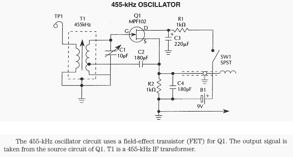
455KHz oscillator using FET & 455KHz IF transformer - The 455-kHz oscillator circuit uses a filed-effect transistor (FET) for Q1. The output signal is taken from the source circuit of Q1. T1 is a 455-kHz IF transformer. __
555 Triangle Waveform Generator - The circuit is a triangle waveform generator that uses as few parts as possible. A 555 timer IC, 2 resistors and two capacitors make the triangle wave. The IC is connected in a 50% duty-cycle astable square-wave oscillator circuit. The square-wave output is fed from pin 3 of the IC to an RC shaping circuit. When the __ Designed by Popescu Marian
555 VCO - By adjusting the voltage on pin 5, (the CONTROL pin) the frequency of the oscillator can be adjusted quite considerably. __ 555-Timer
68HC11 Synthesizes Accurate Sine Wave - 09/02/96 EDN-Design Ideas - You can use a 68HC11 and a 12-bit serial DAC (Figure 1) to generate accurate sine waves without using floating-point arithmetic. Figure 2 shows a block diagram for this sine-wave generator. You can easily analyze the generator's behavior by writing state equations in the z domain. You can also write equations in the
domain. The location of the two poles Design by Mika Maaspuro, Espoo, Finland
8-pin µC forms one-chip programmable VCO - 09/24/98 EDN-Design Ideas - NOTE
: multiple circuits, scroll to this one. The circuit in Figure 1 uses a Microchip 8-pin µC (PIC12C671]as a voltage-controlled oscillator (VCO]. Because PIC12C671 has an internal 4-MHz oscillator, four-channel 8-bit A/D converters, and built-in power-reset circuitry, you need no external components to configure VCO. The µC reads two analog inputs through AN0 and AN1 Design by Yongping Xia, Teldata Inc, Los Angeles, CA
90 MHz voltage controlled oscillator for FM Band - Notice the abundance of 2N4401, 1 k resistors and 330 Ohm resistors? That's because I have a lot of each.2N4401's weren't intended to be used as varactors, but they work just fine. Don't be afraid to experiment with the parts you have on hand. Build this on a ground plane board. Layout is important. __ Designed by Dick Cappels
|